
Reply for method
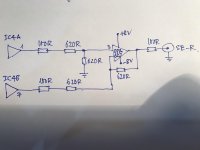
You can try my schematic, this is good method for you!
Hi,
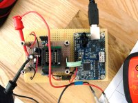
I have 4 PCM1704U-J and JLSound I2SoverUSB board.
I2SoverUSB - I2S over USB Audio
My plan is make a reference DAC which Non-Oversampling, full balanced , XLR and SE two type outputs.
First this circuit base from pavouk.org then returned to balanced type.Can it useable with this way, what is your opinion about circuit? According to this circuit could you recommend a reference I/V Converter, LP filter output? It could be discrete design maybe a transformer. Or these OPA627 and OPA2134P output acceptable for a reference grade?
Also i'm not sure how can i convert XLR outputs to SE outputs, what is best methods for that?
You can try my schematic, this is good method for you!
Attachments
Hi,
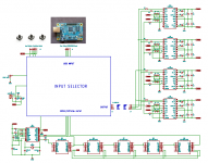
I continue the circuit drawing but have one question to members.I very confused.
First i try to explain circuit. There are a switch circuit between USB and other inputs.When USB close it will connect directly to the PCM1704 side.When SPDIF/Optical input close, it will connect to buffer and bit delay circuit then goes to PCM1704 side.As i know there is no other choise for that.
Then i saw DDDAC notes during my research.They use delay data half clock cycle.My question ;
Do i have to use this half delay circuit or my circuit is enough ?
DDDAC 1794 NOS DAC - Non Oversampling DAC with PCM1794 - no digital filter - modular design DIY DAC for high resolution audio 192/24 192kHz 24bit
http://www.dddac.com/documents/dddac1794pbt_nos_ver51.pdf
Best Regards
Attachments
Hi,
Do you have any progress with the PCM1704 project?
If I use this china xmos usb
New XMOS XU208 USB To Coaxial DAC Digital Interface / I2S Support DSD DOP / HIFI audio/ option Upgrade to 0.1PPM TCXO|usb to coaxial|coaxial dachifi audio - AliExpress
do I need the right/left data alignment circuitry that is part of Pavouk's design?
Thank you.
Do you have a finished PCM1704 dac board or it is in progress?
Actually I know the JL Sound board it is great but if I want to use better oscillators like CRYSTEK CCHD-957 I have to buy additional board from JL Sound for them.
In this china board the oscillators can be replaced easily.
Actually I know the JL Sound board it is great but if I want to use better oscillators like CRYSTEK CCHD-957 I have to buy additional board from JL Sound for them.
In this china board the oscillators can be replaced easily.
I found this board Lusya NOS DAC/I2S format NOS decoder shifter board and I2S data conversion right aligned format DC 5V T0855|Amplifier| - AliExpress which is for XMOS board. So if I want to use china usb xmos board with NOS pcm1704 dacs I must use NOS DAC/I2S format NOS decoder shifter board.
CRYSTEK CCHD-957...NOS....
WIth NOS operation, wouldn't you need something like a 2,8MHz clock ?
- Status
- This old topic is closed. If you want to reopen this topic, contact a moderator using the "Report Post" button.
- Home
- Source & Line
- Digital Line Level
- Any project with PCM1704