Aluminium is flexible, you can counteract the bend with more bolts into the heatsink. The brushed aluminium although an issue, the paste would fill in the gaps. Not the best of thermal junctions but I've seen worse.
Originally, I was going to cut slots in the side panels to allow the Heat Sink Mounting Brackets to be bolted directly to the H/S, but while pondering over the best way to put everything together is when I decided to go with the bolt it all together method, which we now know doesn't work very well.
Today, I had it apart and cut a slot in one side, and have got it back together, but not had chance to see if things have improved, Tomorrow i'll do the other side, and hopefully have chance to run the amps up and see what temps I get.
Sorry all, I’ve been dipping in and out and not reading thoroughly.
Some bad news is that I have studied the pcb layout in post 12 and it is a disaster as far as stability is concerned. It doesn’t surprise me that problems have arisen.
On the bright side you can fix this without having to turn the board; I’ll post what’s needed soon. Fiddly but doable. It should make them sound a lot better too.
Sorry all, I’ve been dipping in and out and not reading thoroughly.
Some bad news is that I have studied the pcb layout in post 12 and it is a disaster as far as stability is concerned. It doesn’t surprise me that problems have arisen.
On the bright side you can fix this without having to turn the board; I’ll post what’s needed soon. Fiddly but doable. It should make them sound a lot better too.
Thank you, Look forward to seeing what you have
")
On the point of Oscillation, I've read a lot of posts where people say their amps oscillate like crazy, and one way to tell is if R15 the 4R7 (3W) resistor gets hot.
R15 on both of my amps doesn't get hot, and I was originally under the impression that any oscillation would be clearly visible on a scope, that was until I found a discussion on another forum where the oscillation is described as being visible on a scope and looking like a slight thickening of the waveform on the falling slope of a sine wave.
I believe I may have observed this on one of the amps the other day, but put it down to the scope being a DSO, they somehow never look as clean as a good old Phosphor scope, If this is the case, I now know what I'm looking for, so can make some better observations, I might even get the manual out to see how I get the image onto a memory stick
Oscillation can be anything from full blown rail to rail output down to a few millivolts of HF at many Mhz. Sometimes it just shows on just side of the output (pos or neg going) and sometimes only above a certain amplitude of output level.
So pretty much any scenario is possible.
So pretty much any scenario is possible.
As Mooly says. Also fuzz on a scope - adjusting focus doesn't cure it. Changing noise levels when you touch ground and power supply lines. Severe oscillation when you put a capacitor across the speaker terminals. Sound is dull/brittle/muddled. Sound breaks up on transients.
It is not good for your amp or the sound quality and in extreme cases can blow a component and melt your speaker.
Four typical causes are:
Poor phase margin of a NFB amp, especially into capacitive loads
Poor grounding, especially high current paths shared with signal grounds. Loops.
Poor decoupling
Crosstalk, proximity of high current conductors to sensitive components
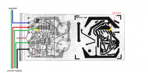
This is my most basic suggestion for improving the Maplin MOSFET amp stability. I've borrowed the PCB diagram from post #12. I've tried to keep it easy to do rather than perfect.
1. Remove C8 and C10. Relocate them underneath the board (not shown) between the drains of each MOSFET and the ground pins of C9/C11. Ideally use 1uF polypropylene.
2. Cut the ground trace as shown in yellow. Make a wide cut - 2mm or more. This separates the zobel network and local decoupling capacitor ground from the input signal ground. Attach a ground wire to where C8 was grounded (green wire).
3. Relocate feedback shunt resistor R6 (1k) so that it connects from C3 neg to where R2 connects to the input ground trace, underneath the PCB (not shown).
4. Wiring. Keep the wiring closely bound, perhaps use cable ties. Keep bends tight.
The purple and brown (shield) are the coax wires that go to the RCA connector on the chassis. Insulate the RCA ground from the chassis. Try to keep the coax signal wire (purple) a cm or more away from the nearby ground wire (green).
The three green ground wires going to the power supply should be soldered as close together at the wire connecting the supply caps to form a star ground. This star ground point can be earthed to the chassis and to mains earth.
Keep the wiring loom of red, black and three greens closely bound all the way to the supply caps.
Do not connect the speaker earth wires together at the speaker terminals. Only at the star point.
Reasons:
a) At the moment the high frequency noise that is decoupled by C8,C9,C10,C11 and the zobel network currents all flows right through the input ground trace and through a ground connection shared with the input ground. Very naughty.
b) The HF decouplers, C8,C10 are a long way (electrically) from the MOSFETs which they are meant to be decoupling. This also creates RF noise loops.
c) The feedback shunt resistor R6 has its ground reference far away from R2.
Note that if your PSU caps are reasonable and your psu wiring is thick and bound, you don't need C9,C11 at all - they don't really do much.
I have more suggestions but I'll let this digest first.
Attachments
This is my most basic suggestion for improving the Maplin MOSFET amp stability. I've borrowed the PCB diagram from post #12. I've tried to keep it easy to do rather than perfect.
1. Remove C8 and C10. Relocate them underneath the board (not shown) between the drains of each MOSFET and the ground pins of C9/C11. Ideally use 1uF polypropylene.
2. Cut the ground trace as shown in yellow. Make a wide cut - 2mm or more. This separates the zobel network and local decoupling capacitor ground from the input signal ground. Attach a ground wire to where C8 was grounded (green wire).
3. Relocate feedback shunt resistor R6 (1k) so that it connects from C3 neg to where R2 connects to the input ground trace, underneath the PCB (not shown).
4. Wiring. Keep the wiring closely bound, perhaps use cable ties. Keep bends tight.
The purple and brown (shield) are the coax wires that go to the RCA connector on the chassis. Insulate the RCA ground from the chassis. Try to keep the coax signal wire (purple) a cm or more away from the nearby ground wire (green).
The three green ground wires going to the power supply should be soldered as close together at the wire connecting the supply caps to form a star ground. This star ground point can be earthed to the chassis and to mains earth.
Keep the wiring loom of red, black and three greens closely bound all the way to the supply caps.
Do not connect the speaker earth wires together at the speaker terminals. Only at the star point.
Reasons:
a) At the moment the high frequency noise that is decoupled by C8,C9,C10,C11 and the zobel network currents all flows right through the input ground trace and through a ground connection shared with the input ground. Very naughty.
b) The HF decouplers, C8,C10 are a long way (electrically) from the MOSFETs which they are meant to be decoupling. This also creates RF noise loops.
c) The feedback shunt resistor R6 has its ground reference far away from R2.
Note that if your PSU caps are reasonable and your psu wiring is thick and bound, you don't need C9,C11 at all - they don't really do much.
I have more suggestions but I'll let this digest first.
Thank you for these suggestions, and actually not to difficult to do either, and I also have the advantage that my power supply and earth wires are already bound together with cable ties, and all Earth wires are connected back at the PSU Caps 0v, I would only need to include the speaker grounds within the loom and add another Ground wire, I also have a handy tag strip nearby to connect the power supply 0v to chassis earth, The RCA connectors are already isolated from the case, so not a problem there.
Last edited:
Reasons:
a) At the moment the high frequency noise that is decoupled by C8,C9,C10,C11 and the zobel network currents all flows right through the input ground trace and through a ground connection shared with the input ground. Very naughty.
.
Either star grounding wasn't invented then or they struggled getting a layout.
I have done numerous pcb designs and learned lessons from them yet my latest project still had a grounding problem. So still learning after 37 years of electronic design.
I always return zobel ground to star ground too.
Good idea. The present arrangement leaves a couple of cms of antennas. An alternative solution for the perfectionist would be to cut the gate traces near the gates and solder SMT resistors across the gaps.Another tip is to move the gate resistors closer to the actual mosfet gates.
by cutting the tracks near the gates, linking out the existing gate resistor position, and remounting the gate resistors directly under the mosfets on the track side.
Tomorrow I’ll look at the circuit and components. I think I may have built one of these back in the 80s. I designed my first amp using bits of this design. Those were the days. I liked those forgiving FETs. I was pretty naive then but somehow it worked ok. One of my school friends still uses one of mine for his hifi.
@Mooly
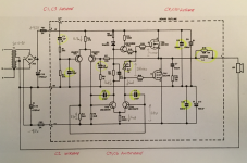
Have you got this circuit in your simulator? If so, how does its phase response look into 8 ohms and 8 ohms in parallel with, say, 1uF and 100nF?
@Mooly
Have you got this circuit in your simulator? If so, how does its phase response look into 8 ohms and 8 ohms in parallel with, say, 1uF and 100nF?
This is my most basic suggestion for improving the Maplin MOSFET amp stability. I've borrowed the PCB diagram from post #12. I've tried to keep it easy to do rather than perfect.
1. Remove C8 and C10. Relocate them underneath the board (not shown) between the drains of each MOSFET and the ground pins of C9/C11. Ideally use 1uF polypropylene.
Just a quick question / observation, Relocating C8 & C10, Would it be best to connect directly to the Drain Pins of each MosFet, or just as close as possible? Either way I would probable need to use an Axial style cap.
Also, 100nf to 1uf, That's a big jump, but I'm no expert
Tomorrow I’ll look at the circuit and components. I think I may have built one of these back in the 80s. I designed my first amp using bits of this design. Those were the days. I liked those forgiving FETs. I was pretty naive then but somehow it worked ok. One of my school friends still uses one of mine for his hifi.
I'll never forget how much better these amps sounded compared to my old Trio KA-305, I disconnected the main amp of the Trio and used the pre amp to drive these amps, Bass was much tighter and had a overall warm sound, several of my friends built some of these amps after hearing mine.
The caps don’t need to be close to the drain pins. Anywhere between drain and ground will be a big improvement on where they are now.Just a quick question / observation, Relocating C8 & C10, Would it be best to connect directly to the Drain Pins of each MosFet, or just as close as possible? Either way I would probable need to use an Axial style cap.
Also, 100nf to 1uf, That's a big jump, but I'm no expert
I’m not convinced 100nF was a carefully considered choice in the first place. Nowadays, a 1uF polypropylene is a practical size but you can use smaller if it is easier or fits better. Axial is handy but rectangular/radial on its side is fine. You could also replace the two electrolytics with radials but it might be tricky to get the pin spacing the same.
More about parts choices soon...
Last edited:
I look forward to seeing what else you think will improve things so will hold off ordering any parts just yet.
Something I may do if I start to mod these boards is replace RV1 with a 10 turn Cermet type variable resistor, setting 50ma is very tricky as the wiper is almost in its full clockwise position, I don't know if anyone else has noticed this.
In the meantime, I have a 1:1 or thereabouts scale printout of the track layout so can see what style of caps would be most practical, and also look as though they were supposed to be there, I do like things to look nice
New Mosfet Amp design
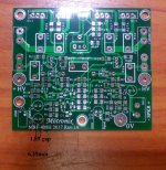
i decided to design new mosfet amplifier with TO220 Mosfet transistors. the performance and stability much better then the old mosfet amplifier that i have. here is picture without parts if someone want to see it with parts let me know i will upload full assembly picture
i decided to design new mosfet amplifier with TO220 Mosfet transistors. the performance and stability much better then the old mosfet amplifier that i have. here is picture without parts if someone want to see it with parts let me know i will upload full assembly picture
Attachments
Some more suggestions regarding components.
You should do...
1. Nearly 40 years old...time to replace C1 and C3! I like Nichicon ES series.
2. C2 is rather small. A larger value, up to 470pF, would make a much better RF filter. Try WIMA FPK2 for a fit or a polystyrene.
3. New trimmers. What are your supply voltages? I estimate for +/-42V rails that the average current through RV1 will be about 5mA. The 2SK133 and 2SJ48 datasheets suggest you don't need more than 3V across RV1. So worst case, 600 ohm trimmers; but you could very likely get away with 500 ohm (standard) to give yourself more adjustment range. The gate thresholds obviously vary widely among devices.
4. R13 & R14 moving closer to the gate pins has already been suggested. For cosmetic reasons you could back-fill the original slots with small value resistors rather than wire links. Or use 47-ohm + 47 ohm or whatever.
You might do...(uncertain audible benefit for this circuit)...
5. C5 & C6 might need increasing to improve the phase margin. I'm waiting to hear from Mooly to confirm this.
6. C5 & C6 could use a decent dielectric like polystyrene or polypropylene.
7. Optionally, relocate R16/L1 to the speaker terminal at the chassis. Mount it with axis vertical.
Attachments
Last edited:
It is a modest design of limited potential but we can't help loving our first amp builds! So it feels like we owe them some spit and polish to try to squeeze the best out of them.I'll never forget how much better these amps sounded compared to my old Trio KA-305, I disconnected the main amp of the Trio and used the pre amp to drive these amps, Bass was much tighter and had a overall warm sound, several of my friends built some of these amps after hearing mine.
Last edited:
- Status
- This old topic is closed. If you want to reopen this topic, contact a moderator using the "Report Post" button.
- Home
- Amplifiers
- Solid State
- Any Maplin MosFet Amp Guru's on here?