Yeah, and build a separate power supply (transformer, rectifier, caps) at more cost , more complexity and require more room in the chassis....if I am going to go thru all that, I will build a class A amp....
I moved on from Hypex anyway (built at least 15 of them). I believe the ICEpowers are superior anyway...but we digress...yes?
I moved on from Hypex anyway (built at least 15 of them). I believe the ICEpowers are superior anyway...but we digress...yes?
yes the PS is broke, don't do a band-aid fix, find the real problem.
Sounds like the house keeping (controller) supply is wonky. most likely this DC is supplied by the line V then switches over to winding from the switcher.
Get the PS schematic and/or swap the unit to the vendor.
Sounds like the house keeping (controller) supply is wonky. most likely this DC is supplied by the line V then switches over to winding from the switcher.
Get the PS schematic and/or swap the unit to the vendor.
Last edited:
Get the PS schematic and/or swap the unit to the vendor.
Absolutely zero chance of manufacturer help...I am sure ICEPower couldn't care less about helping....
OK, got a little ballsy tonight. I took a 5.6uf 200v Sprague Orange Drop in series with the mains. 123VAC on one side of the cap, and 106VAC on the other. Great. The amp fired right up. If I use 10uf, I should be right around 10VAC drop, but its fine at 106VAC
I did not leave it like this for more than a couple minutes, as i do not know what the mains phase change due to the cap is doing to the SMPS...
Other than that, if the cap ever fails (shorts), the amp will go into over-voltage protection and not enable, so is there a downside keeping series cap on mains?
Comments??
Last edited:
Have you measured the voltage under full load ? A 10uf cap has a reactance of over 300 ohms at 50Hz. You are not going to pull much current through that. The amp will see a constantly fluctuating voltage and may misbehave if the voltage falls to low (possibly destructively).
A variac gives a very slow rate of change of voltage, the cap will cause the voltage to be modulated much more quickly.
OK, maybe using the word destructively is looking on the bleak side, but I've also seen how some PSU's react when started up slowly (and they can latch destructively)
I would definitely be looking at a proper fix for this... the cap is a poor solution as a permanent arrangement I'm afraid. That's why I mentioned trying to see what technology (IC etc) it uses. The "fix" may be as simple as changing the value of a resistor.
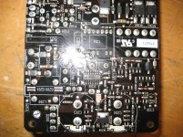
identify the controller IC (16 pin SOIC ) it's located on the rear side. Find the part # then trace out the circuitry from the Vcc pin to the line input. These house-keeping supply circuits are usually simple but complex in their own way.
IDK if the SMPS worked properly before but look for solder bridges, missing or burned parts, backwards polarity caps / diodes , IMO it probably has a wrong value part installed nearby. esp. look at zener diodes to normal diode misplacement if any.
IDK if the SMPS worked properly before but look for solder bridges, missing or burned parts, backwards polarity caps / diodes , IMO it probably has a wrong value part installed nearby. esp. look at zener diodes to normal diode misplacement if any.
I see that the two large caps on bottom. The neg of the one to the right in pic is grounded to pin 12 of IC300 (gnd), while the other cap to left neg is not...only thing seems odd...
Should ground of IC300 (pin 12) connect to ground of PCB to chassis? It does not.
Should ground of IC300 (pin 12) connect to ground of PCB to chassis? It does not.
Last edited:
The two caps could be in series with the primary of the chopper transformer connected to the junction of the two. That's a fairly common connection method. Pin 12 of the IC is (primary) ground.
I'm sorry... I just don't see anything obvious where I would be confident to say "try this". I think whatever connects to pin 10 could be the clue though.
I'm sorry... I just don't see anything obvious where I would be confident to say "try this". I think whatever connects to pin 10 could be the clue though.
The two caps could be in series with the primary
Yes, the big caps are in series.
Don't know if I mentioned this, but this is SE version, where the ground for the speaker outs are connected.
That sounds fairly typical. Hmmm I dunno. Not that I can see anything obvious but does pin 10 (that's the one above the A on the part number on the IC) go to the resistor marked "682" (a 6k8) to the right of the IC. Just curious.
I'll look again later at this, but finding a similar implementation drawn out somewhere might help.
I'll look again later at this, but finding a similar implementation drawn out somewhere might help.
- Status
- This old topic is closed. If you want to reopen this topic, contact a moderator using the "Report Post" button.
- Home
- Amplifiers
- Power Supplies
- Any easy way to reduce mains from 122VAC to 110VAC?