what about this approach?
http://www.diyaudio.com/forums/solid-state/155939-mosfet-relais.html
http://www.diyaudio.com/forums/solid-state/155939-mosfet-relais.html
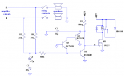
R5 & R6 bring down the offset current to non damage levels.
The two resistors allow just 1.1mA to pass from 50Voffset to the good channel.
Of course. 44Kohm resistance between left and right output. This seems a lot simpler than the first schematic I posted with all of the diodes, and obviously the FET will hold it self on until the power is removed, therefore no need for a PIC at all.
The gate of Q2 is connected to ground! How can this ever switch?
And can +25v be used instead of 12v?
Q1 detects positive dc voltage.The gate of Q2 is connected to ground! How can this ever switch?
And Q2 detects negative dc voltage.
To switch ON Q2 you need 0.6V between base and emitter.
So If we connect base of a Q2 to GND (0V) we need -0.6V on emitter to switch ON Q2.
C1 provides soft-start and C2, C3 can be replaced by one electrolyte capacitor because all electrolyte capacitor can handle -0.7V for a short period of time.
yes you can.And can +25v be used instead of 12v?
Hi Hugh,
Thanks for the compliment... one of these days I might actually get around to a new amp build... and then take this further.
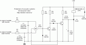
The 6.8meg and 47pf roll the HF off considerably. I went for such values to avoid any possible criticism that the circuit loads the volume pot at all, or could introduce any non linearity.
Thanks...
Thanks for the compliment... one of these days I might actually get around to a new amp build... and then take this further.
The 6.8meg and 47pf roll the HF off considerably. I went for such values to avoid any possible criticism that the circuit loads the volume pot at all, or could introduce any non linearity.
Thanks...
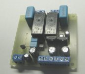
jony, I built the circuit. When I power it, the relay energizes. When I put + or - volts to the input, the relay clicks off and stays off even when I remove the + or - from the input. So it seems to be working..... Now, to reset the circuit, the power needs to be removed and then re-applied. When I do this, it takes forever for the relay to energise. If I remove the 2 x 47uF caps, everything works the same and the circuit resets immediately after the power is applied.
Is this normal?
Is this normal?
Ok. I'm not sure what is actually going on....
I have a 1meg resistor as in the original diagram, connected to a 1uF cap. and 2x 10uF caps connected in reverse where the 47uF caps are in the diagram.
When I first connect, there is a slight delay and the relay energises.
When I put + or - onto the input, the relay de-energises (OK so far)
I remove the + or - and after 4 or 5 seconds, the relay energises again, shouldn't it stay de-energised until I cycle the power on and off to it? (Or am I getting MOSFETS and Thyristors mixed up her?)
Last edited:
This delay is cause by C1When I first connect, there is a slight delay and the relay energises.
seems OK for my.I remove the + or - and after 4 or 5 seconds, the relay energises again,
To achieve this you need softly modify the schematicshouldn't it stay de-energised until I cycle the power on and off to it?
Attachments
One minor catch in setups with both amps feeding the circuit through a resistor. (This actually happened to me in an old Nikko reciever). I had one output go to the positive rail, and the other going to the negative rail, and the protect circuit had zero volts goin in, so it energized the relay!. (Problem was due to broken ground connections on the input wires going into the circuit board.) Murphy's law in action.
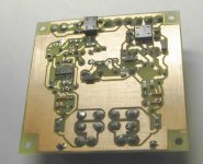
Just in case anyone wants to have a look, here is a link to a page from the chip amp photo thread of my Gainclone:
http://www.diyaudio.com/forums/chip-amps/79303-chip-amp-photo-gallery-137.html
http://www.diyaudio.com/forums/chip-amps/79303-chip-amp-photo-gallery-137.html
A second amp with such DC protect there is - also from elektor. Title "The Current Amp" Nov/Dec 1992. Load impedance: 400 mΩ load and 35A peak output current. Also available in french:
http://209.85.129.132/search?q=cach...current+Amp"+elektor&cd=5&hl=de&ct=clnk&gl=de
(scoll down)
hallo tiefbassuebertr,
hast du eventuell den Schaltplan vom Current Amp aus 92, der Link geht leider nicht, besten dank.
LG susannsusann
hello tiefbassuebertr,
You may have the circuit diagram of current amplifier from 92, the link is not live, thank you.
LG susan Susan
English please
dave

Q1 detects positive dc voltage.
And Q2 detects negative dc voltage.
To switch ON Q2 you need 0.6V between base and emitter.
So If we connect base of a Q2 to GND (0V) we need -0.6V on emitter to switch ON Q2.
C1 provides soft-start and C2, C3 can be replaced by one electrolyte capacitor because all electrolyte capacitor can handle -0.7V for a short period of time.
yes you can.
Hello all,
Regarding to circuit at post #37, can i connect more than two channels each with 22k resistor additionaly via proper relay?
Thanks.
Last edited:
- Status
- This old topic is closed. If you want to reopen this topic, contact a moderator using the "Report Post" button.
- Home
- Amplifiers
- Solid State
- Another simple DC protection