So for the 2SA970 would the Zetex ZTX795A be the appropriate sub?
Do the drivers need to be matched? I'm still fuzzy on that.
I'd say 2SA970 would be a good sub for 2SA970 (2SA970 - MCM Electronics Search)
I'd say 2SA970 would be a good sub for 2SA970 (2SA970 - MCM Electronics Search)
The problem with that part is it does not specify the grade, and the spec calls for GR or BL. I managed to find both the 2SC2240 and the 2SA970 at GR or BL grade at this place:
TV Parts Stereo Parts Electronic Parts Flyback Transformers Optical Pickups Japanese Semiconductors Transistors ICs Tools Tech Aids
They were very responsive to my emails, so I hope the parts are as good as the service (and better than their website!).
B&D, whom I've dealt with for years, and have great confidence in, also carry the 2SA970BL's
B&D Enterprises: Search
B&D Enterprises: Search
Well, I got the transistors from Acme very rapidly. The 2240's are fine, but all the 970's, even though they are marked BL, have a gain of only about 145 hfe.
Is that too low to use? Or just less than optimal? My ears have been less than optimal for at least a decade, so....")
Is that too low to use? Or just less than optimal? My ears have been less than optimal for at least a decade, so....
Last edited:
Well, I got the transistors from Acme very rapidly. The 2240's are fine, but all the 970's, even though they are marked BL, have a gain of only about 145 hfe.
Is that too low to use? Or just less than optimal? My ears have been less than optimal for at least a decade, so....
Q8s job appears to be a drive limiter for Q7. I believe the 'lower' gain will not be an issue for Q8. Perhaps Mr. Pass will verify this. If it were mine I'd fire it up and enjoy.
G²
Well, fire it up was not a good choice of words. I replaced Q7 and Q4, as well as Q8 (with the "under-gained" 970) and R7 and R8. Plugged it in and turned it on and almost immediately R22 (the big 2 watt resistor) got hot enough to release the damn magic smoke.
Very discouraged.
I've double checked every replaced component for correct orientation, and I've checked every solder joint under the magnifying glass. Nothing seems amiss. I just don't know what I could have done wrong.
So sad.
Very discouraged.
I've double checked every replaced component for correct orientation, and I've checked every solder joint under the magnifying glass. Nothing seems amiss. I just don't know what I could have done wrong.
So sad.
Well, fire it up was not a good choice of words. I replaced Q7 and Q4, as well as Q8 (with the "under-gained" 970) and R7 and R8. Plugged it in and turned it on and almost immediately R22 (the big 2 watt resistor) got hot enough to release the damn magic smoke.
Very discouraged.
I've double checked every replaced component for correct orientation, and I've checked every solder joint under the magnifying glass. Nothing seems amiss. I just don't know what I could have done wrong.
So sad.
Do you have an O'scope? R22 looks to be part of the Zobel network. The only way to get it hot is for the amp to oscillate at a pretty high frequency _or_ for C6 to be shorted _and_ high DC ouput to be present.
A little paranoia isn't a bad thing in high power amplifiers as there is no room for mistakes. Beware of substitute parts with different pinout and with what you've gone through, I'd even check exact replacements.
Long ago I worked on a broadcast TV camera that other techs were trying to get working. A Zener diode had failed and the replacement part had an 'R' suffix. After trashing several hundred dollars of power transistors they gave it to me with the last pair of transistors they had. I checked everything that had been changed and found the reverse diode so I swapped the leads and fired it up. No magic smoke, it worked and I got changed from part time to full time.
G²
Doesn't look like anything to do with the Zoebel to me. I see R22 as feeding base current through an offset adjustment pot to Q8 (one of the 2SA970's).
Is Q8 still OK?
Where is R21 set?
If you're ever likely to work on any other amps, a Variac would be a worthwhile investment.
Is Q8 still OK?
Where is R21 set?
If you're ever likely to work on any other amps, a Variac would be a worthwhile investment.
On second look, some other information must be missing here. R22 shows as 5.6K 1W on the schematic I got from audio circuit. It's got -62V on one end, and, potentially, the base of Q8 on the other. Even if Q8 were shorted BC, the difference across R22 would be only 18V, which would account for .06W through that path.
I think the problem has to be more around Q10, Q11, or Q12. If one (or more) of them were short, they'd pull 80V across R20, R21, R22, and R26, with the bulk of the power being dissipated by R22.
Also check Q10 to make sure some adjustment, or problem with Q9, is not pulling it full on.
BTW, assuming I calculated right, even at that point, R22 should be dissipating only .6W. Which is within its power rating. If R20 and R21 were somehow shorted (which is nearly impossible), AND Q10 or Q11 or Q12 were pulling the other end of R22 to -80, R22 would then be dissipating 1.14W: just beyond its 1W power rating. This shouldn't be enough to smoke it, although it would get mighty hot. Please make sure the resistor we're talking about is R22 and is of the correct value.
Last edited:
So, third look:
Since it doesn't make sense for the regulation section of the PS to account for overloading R22 all by itself, I think there has to be an interaction with the output section.
Can you disconnect the output section and check the + and - 62V outputs from the regulator unloaded?
If the output section were shorted and pulling the -62V rail up to +62V, that would put enough load on R22 to smoke it... though I would have thought it would smoke R7 as well.
Knowing whether the regulation section is correctly supplying +/- 62V will make things easier to troubleshoot from here.
BTW, now I see why stratus thought R22 was part of the zoebel... it is. Well, there are R22's in both the audio schematic and the power supply schematic. I expect, though, that you're talking about the one in the power supply.
On second look, some other information must be missing here. R22 shows as 5.6K 1W on the schematic I got from audio circuit. It's got -62V on one end, and, potentially, the base of Q8 on the other. Even if Q8 were shorted BC, the difference across R22 would be only 18V, which would account for .06W through that path.
I think the problem has to be more around Q10, Q11, or Q12. If one (or more) of them were short, they'd pull 80V across R20, R21, R22, and R26, with the bulk of the power being dissipated by R22.
Also check Q10 to make sure some adjustment, or problem with Q9, is not pulling it full on.
BTW, assuming I calculated right, even at that point, R22 should be dissipating only .6W. Which is within its power rating. If R20 and R21 were somehow shorted (which is nearly impossible), AND Q10 or Q11 or Q12 were pulling the other end of R22 to -80, R22 would then be dissipating 1.14W: just beyond its 1W power rating. This shouldn't be enough to smoke it, although it would get mighty hot. Please make sure the resistor we're talking about is R22 and is of the correct value.
We're literally on different pages here. The schematic I have is out of a booklet from Adcom. The parts list says 'Input/Driver P.C. Board (A020 A)'. R22 is listed as 5.1 ohm 2 Watt metal oxide film. On my print C6 is 0.1uF film cap. C6 and R22 are in series with C6 to the output and R22 to ground.
I don't know which (or either) of us has the schematic that is in Fredlf's unit.
G²
On second look, some other information must be missing here. R22 shows as 5.6K 1W on the schematic I got from audio circuit.
Please make sure the resistor we're talking about is R22 and is of the correct value.
Hi, thanks for sticking with me.
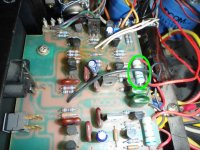
The resistor is definitely 5.1 ohm 5%, according to the color code on the part itself. In my service manual, R22 is listed as 5.1 ohm, 2w. I've circled it in the attached pic.
Since I removed and reinstalled Q11, I'm suspicious of it. If I replace it, it has to be matched to Q12, correct?
I'll test the transistors I installed and post the results soon.
I know, I need a Variac. And a 'scope. And the skills to use one... working on it...
Attachments
So, third look:
Can you disconnect the output section and check the + and - 62V outputs from the regulator unloaded?
I can disconnect the output section by simply pulling the fuses on the output boards, right?
I don't know how to check the outputs from the regulator because I'm not sure what to measure, or where. *sigh* Would it be the + probe lead on the supply of the output board and - lead to ground?
We're literally on different pages here. The schematic I have is out of a booklet from Adcom. The parts list says 'Input/Driver P.C. Board (A020 A)'. R22 is listed as 5.1 ohm 2 Watt metal oxide film. On my print C6 is 0.1uF film cap. C6 and R22 are in series with C6 to the output and R22 to ground.
I don't know which (or either) of us has the schematic that is in Fredlf's unit.
That is what my service manual says as well. Does your manual refer to Front End PC Board 72-2174-0-1?
If so, we have the same manual. Unfortunately, the actual PCB in my amp is an earlier rev., 72-2174, and some of the components are slightly different (e.g. C3).
Well, like I said, there are 2 R22's, one on the analog board (which I guess is the "input board") and one in the PS regulation section. To make things more confusing, both boards have 2SA970's in locations labelled Q8.
The photo, and the value, definitely clears things up, though.
Everything I said previously was regarding the "other" R22, so we can ignore all that.
As stratus said, then, this R22 is part of the zoebel circuit. To smoke, either the amp is oscillating heavily at pretty high frequencies. (Rail to rail oscillations at 30KHz would be around the minimum to get 2W into that resistor.) Or C6 is short.
Have you checked C6?
As stratus said, then, this R22 is part of the zoebel circuit. To smoke, either the amp is oscillating heavily at pretty high frequencies. (Rail to rail oscillations at 30KHz would be around the minimum to get 2W into that resistor.) Or C6 is short.
Have you checked C6?
1. To check C6 it needs to be out of circuit, right?
2. I have some of these, they should work as a replacement, eh?
3. Would a bad Q11 cause such an oscilliation?
thanks as always
Last edited:
1. To check C6 it needs to be out of circuit, right?
2. I have some of these, they should work as a replacement, eh?
3. Would a bad Q11 cause such an oscilliation?
thanks as always
1. Not neccessarily. I'd check first in circuit to see if it looks like it might be low resistance or short. If I only read a few Ohms or less across it, I'd then pull it to see how it reads out of circuit.
2. Yes.
3. Sorry, no idea.
- Status
- This old topic is closed. If you want to reopen this topic, contact a moderator using the "Report Post" button.
- Home
- Amplifiers
- Solid State
- Another high DC Adcom GFA-555