The input of this amp is DC coupled and therefore you should not short the input when testing for DC offset:
http://www.diyaudio.com/forums/soli...r-high-dc-adcom-gfa-555-a-60.html#post2157467
It relies on the preamp output cap to block the small input DC offset.
http://www.diyaudio.com/forums/soli...r-high-dc-adcom-gfa-555-a-60.html#post2157467
It relies on the preamp output cap to block the small input DC offset.
A win for DIY Audio!
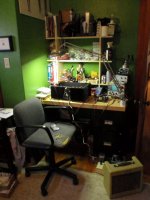
The attached pic is of my Adcom GFA-555 playing the Drive-By Truckers off of my iPod and through a craptacular Fender guitar amp 8" speaker. It sounds sweeter than anything else in the house right now.
Yep. Fixed.
You can hear for yourself here: MobileMe Gallery
Ran through the bias procedure no problem. I'll check it again tomorrow and do the other channel. I'll see what the final DC offset figures are.
I can't say enough how grateful I am to Chris, David, Glenn, Paul, Pete, Steve and everybody else who chimed in on this epic thread. This was a monumentally bad idea on my part, no one so inexperienced should have attempted such a repair, especially given the confounding factor of counterfeit parts. But those long odds were beaten by the generosity of everyone who took the time to hand-hold me. Thanks.
I'm going to let it burn-in for a few hours and treat myself to a plus-sized gin and tonic.
cheers,
Fred
Attachments
Last edited:
Ran it for 4+ hours yesterday, no problem.
Final DC offset: 29mvdc
It'll get it buttoned up and returned to service this evening. At some point in the future I'll rebuild the output sections on both channels and replace the remaining original drivers. Now that I've done the procedure, I can see replacing the bias pots with multi-turn sealed units, too. Those factory pots suck, frankly.
But next, I need to build transistor testing jigs and hit the books. Especially the books.
Isn't the servo in these amps supposed to get output offset down to +/-5mV or 10mV? Not that 29mV is really a problem, just wondering.
Great job by the way.
That model, at least the early ones, didn't have the servo.
Hi Fred,
Congrats!
You persevered and completed a difficult repair. You bucked some additional problems that no one should have to deal with on top of that.
You deserve a great deal of respect for both hanging in there, and doing a good job on the repair. I think you will have more than just a bit of fun with your new hobby. You have the aptitude for it.
Hi Steve,
Yep, that model doesn't have a DC servo. This makes a matched pair of 2SC2240BL transistors more meaningful. Matching these has a direct effect on the distortion products the amplifier generates. Normally matching can greatly reduce the amount of DC offset too, but in this case there is another overriding factor. See next paragraph ...
Hi Pete,
Yep, I completely forgot this on has no input blocking capacitor. If that amp were mine, I would install one straight off. The very last thing you need is an amp that is sensitive to the resistive load on it's input! Just imagine the person that unplugs the RCA cables with the amp on and speakers connected. Could generate an unpleasant BANG.
I don't think that using shorting plugs is the wrong thing to do though. Most preamps do have a low impedance output (I hope) if they lack a coupling capacitor. Krell comes to mind, not even with their preamplifiers. The only way to stabilize the DC offset on the output of this amplifier is to have a DC blocking capacitor to isolate the DC resistance as seen by the differential pair. Make no mistake, there most certainly will be a DC voltage across the RCA input connector.
-Chris
Hi Fred,
Here is a link to to a site that covers the basics of amplifiers and amplifier design. If you would like to tackle LTspice or another, spice files of all the circuits are included.
This is a good place to start.
Circuit Collection
David.
Here is a link to to a site that covers the basics of amplifiers and amplifier design. If you would like to tackle LTspice or another, spice files of all the circuits are included.
This is a good place to start.
Circuit Collection
David.
Thanks David, I'll check that out. If there's not one already, think I might start a thread about members' favorite books and other educational resources. E.g., Electronics for Earthlings is a must-have for wet-behind-the-ears noobs like me, imho.
Returned the Adcom to service yesterday. It sounds good. There is a distinct difference between the rebuilt channel and the "old" channel. The new channel sounds more open and natural, the old channel is a little more closed-in and treble-forward, but has a little more low-end (that could be speaker placement in part). Not surprisingly, the imaging is all smeary. So it will do duty as a sub amp (NOT in bridged mode!) until I can rebuild the old channel. At least I won't have to buy many parts!
Chris, how would you install a blocking cap on this amp? I'm guessing the pc mount input jacks would have to get changed for chassis mount, for starters.
Hi Fred,
No, you would cut a trace and mount the capacitor across the cut. You need to install a resistor from the RCA signal to ground so the capacitor can charge properly. Use a good quality bipolar capacitor, but the value will be large. I should really look at this more closely since this particular situation is not ideal from a capacitor standpoint. It's almost ugly enough to require a buffer in order to drive the input due to the low impedance there.
While you are at it, buy some 2SC2240 bl (<--- gain rating) transistors and match them carefully. Replace the originals in both channels and tie them together thermally. This can improve the sound quality as long as the pair can remain balanced. You should buy about 20 pcs. These are popular parts, and are known as high quality for input pairs. They would work really well in DIY projects as well.
-Chris
No, you would cut a trace and mount the capacitor across the cut. You need to install a resistor from the RCA signal to ground so the capacitor can charge properly. Use a good quality bipolar capacitor, but the value will be large. I should really look at this more closely since this particular situation is not ideal from a capacitor standpoint. It's almost ugly enough to require a buffer in order to drive the input due to the low impedance there.
There shouldn't be unless you have changed some part types.There is a distinct difference between the rebuilt channel and the "old" channel.
Thank you! Wise choice.(NOT in bridged mode!)
Now that's the way to handle this problem!... until I can rebuild the old channel.
While you are at it, buy some 2SC2240 bl (<--- gain rating) transistors and match them carefully. Replace the originals in both channels and tie them together thermally. This can improve the sound quality as long as the pair can remain balanced. You should buy about 20 pcs. These are popular parts, and are known as high quality for input pairs. They would work really well in DIY projects as well.
-Chris
Hi Fred,
It is possible that the speaker connected to the channel that failed took some damage.
Speakers don't do well with DC. How long was the DC present at the output before the fuse blew?
I have repaired thousands of power amps in my career and I have never heard an audible difference between channels after a repair even when it was necessary sub parts.
Try switching the speakers from one channel to the other or running a mono signal through both channels.
Hi Fred,
It is possible that the speaker connected to the channel that failed took some damage.
Speakers don't do well with DC. How long was the DC present at the output before the fuse blew?
.
I have had an amp fry before and it sounded different through a pair of speakers I had. Turned out one speaker had partially fried as well and was a lower impedance than its matching piar.
I now always add a DC protect circuit to my amps. Its just a simple PIC monitoring how long the siganl stays in either phase. If it detects DC for 500ms it shuts off the output relay. It has saved a fortune in speakers.
Well, I sat down for a more focused, saturday afternoon sort-of listening session. With different sources, the difference between the channels is far less than I thought at first. I still think I hear something, but it's subtle enough it could just be the vagaries of room placement and the power of suggestion.
That said, the old channel still has the original drivers, which I replaced with OnSemi subs in the new channel, and the old channel still has the original 'lytics, whereas all the caps were replaced in the new channel. Some of the old ones I pulled had drifted from their rated spec. Some of the TRs I pulled also had specs out of range (low gain), so they were no longer well matched. There's no reason to assume similar conditions don't exist in the old channel. As Chris said, matching influences the distortion products and those, in my understanding, is what really colors sound. Who knows? My ears are more olden than golden these days anyway. It probably won't be long until a sub-amp is all I need. <grin>
And yeah, I swapped the speakers (KEF Q-75's, FYI), they're both fine. Phew.
Nigel, I'd be interested in learning more about that protect circuit. Have you discussed it elsewhere?
Last edited:
Nigel, I'd be interested in learning more about that protect circuit. Have you discussed it elsewhere?
It works on the pricipal that the PIC running off 5 volts has an input pin threshold of 2 volts. I put a potential divider off the output into one input pin and the same for another pin. One potential divider goes to zero volts while the othe]r goes to 5 volts. The positive phase works into the potential divider going to zero volts and the negative phase goes to the potential divider going to 5 volts.
The PIC then looks at the input pins and if one goes above 20 volts or the other goes to minus 20 volts for more than 500ms it turns off the speaker relay.
An externally hosted image should be here but it was not working when we last tested it.
Last edited:
I have had an amp fry before and it sounded different through a pair of speakers I had. Turned out one speaker had partially fried as well and was a lower impedance than its matching piar.
I now always add a DC protect circuit to my amps. Its just a simple PIC monitoring how long the siganl stays in either phase. If it detects DC for 500ms it shuts off the output relay. It has saved a fortune in speakers.
I totally agree with this. I have a pair of vintage Tannoys and the thought of damaging them is not welcome. It's hard to find parts for them and if I can the parts are outrageously expensive.
Some audiophiles don't like relay contacts between there amps and speakers. They claim there is an audible difference. Douglas Self did some tests on this and claims it is unfounded.
David.
Well, I sat down for a more focused, saturday afternoon sort-of listening session. With different sources, the difference between the channels is far less than I thought at first. I still think I hear something, but it's subtle enough it could just be the vagaries of room placement and the power of suggestion.
That said, the old channel still has the original drivers, which I replaced with OnSemi subs in the new channel, and the old channel still has the original 'lytics, whereas all the caps were replaced in the new channel. Some of the old ones I pulled had drifted from their rated spec. Some of the TRs I pulled also had specs out of range (low gain), so they were no longer well matched. There's no reason to assume similar conditions don't exist in the old channel. As Chris said, matching influences the distortion products and those, in my understanding, is what really colors sound. Who knows? My ears are more olden than golden these days anyway. It probably won't be long until a sub-amp is all I need. <grin>
And yeah, I swapped the speakers (KEF Q-75's, FYI), they're both fine. Phew.
Nigel, I'd be interested in learning more about that protect circuit. Have you discussed it elsewhere?
Hi Fred,
There should be no audible difference between the two channels. I do suggest that when you are ready for a second round, to at least change the drivers on the other channel and all the electrolytic caps. Checking the other driver board transistors for low beta might also be a good idea, and matching the diff pair as you did with the other channel. I would use a film blocking cap on the input 10 uF should do. You could lift a lead on R1 and put the cap in series without having to cut any trace.
I would reduce the rail fuses on both channels as a simple way to protect your speakers, you can probably get by with 3A if you use 8 ohm speakers, unless you really drive it hard. The extra power then just serves to handle peaks without clipping.
The DH-500 has a simple DC protect circuit:
http://www.hafler.com/techsupport/pdf/DH-500_amp_man.pdf
Last edited:
Hey, I'm happy Fred you got the sucker to work. Sorry I didn't post a word - my PC got "hi-jacked", damn XP, and I lost capability to login as well as some files, etc. Nice tool the IT-18, solved a lot of guess work for you - I wish to have one. If you can go with the new set of MJ211xx, then maybe the amp would really be capable of running low Z and in the brigde mode. You can put second pair of RCA inputs for capacitor blocking, I guess, so you can have a choice between DC and cap coupling. I'm not a expert like Anatech, PB2, and others - I have a lot to learn from them. Maybe you can put cooling fan as well to keep the heatsinks cooler when you crank the dBs up.
Hi Dave, all,
I suspect that those people who can hear the relay are either using the wrong type of relay (some have been shown to generate THD when the speaker current flows through the frame - from Douglas Self), or the existing relay is damaged or oxidized (read: old). Like everything else, relays do require cleaning or replacement if the contact plating is damaged. Base metal doesn't work well for making low resistance contacts. Another great way for relay contacts to become damaged are the great techs who use emery boards or tools used for contactors on normal relay contacts. Others who use contact cleaner and leave it on the contacts also shorten the life of a relay (the cleaner burns in arcs, building up an insulating layer).
Another thing to think about is that relays have far less effect on the signal to the speakers than something like a fuse will. Even those gold "audiofool" fuses are thermal devices with a highly non-linear resistance vs temperature curve.
Hi Pete, Fred,
Yup. The caps or xistor matching might be at the bottom of the slight audible differences. Too bad you didn't have a good THD meter there Fred. You could measure before and after going over the channel. For what it's worth, I have measured slight THD performance improvements after "doing my thing" with an amplifier. After all, the product did perform well enough. It's not like they sounded really bad. The fact that I could actually measure a slight reduction in distortion after hearing the improved sound quality was heartening (and a surprise). I guess it doesn't take much to make an audible difference, and the fact that it's difficult to measure tends to explain the confusion some people have over listening tests and measurements. I maintain that they are both very important to do, only one or the other can lead you astray will designing.
-Chris
- Status
- This old topic is closed. If you want to reopen this topic, contact a moderator using the "Report Post" button.
- Home
- Amplifiers
- Solid State
- Another high DC Adcom GFA-555