")
That sounds "sound"!
I will do that sometime soon.
Anyone a view on volume per unit, 1.1litres is current, easy to get to 1.6, whats optimum?
M
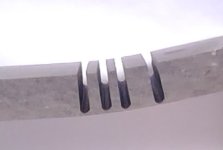
I just did a test slice on MDF, to bend the corners on the side as opposed to joint and round it.
There is a lot of void after slicing and although i would not cut quite as deep it would be a messy glue fill to hold the bend and not much real structure left. is it better to joint and shape the outside?
M
I will do that sometime soon.
Anyone a view on volume per unit, 1.1litres is current, easy to get to 1.6, whats optimum?
M
I just did a test slice on MDF, to bend the corners on the side as opposed to joint and round it.
There is a lot of void after slicing and although i would not cut quite as deep it would be a messy glue fill to hold the bend and not much real structure left. is it better to joint and shape the outside?
M
Attachments
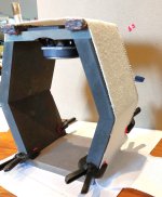
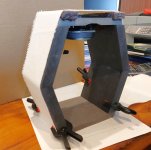
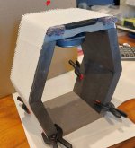
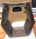
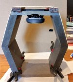
Having now made a section of cabinet, I have decided to stick with a hexagon section, so i made that section as per photos attached.
Each driver section will be split from the next by an 8mm mdf divider, the sides will be 12mm mdf, the same as the baffle and rear in the pics. I made them of 19mm today because that was at hand. Then with the same external dimensions this is a 2litre per driver cabinet. i assume this addresses the point made by Freedom above?
Each section will be lined with the same felt as the driver surround.
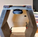
I have one small problem to consider where the router relieved mounting hole crosses the divider, seen as a part circle on the baffle back in the pictures.
I remember discussions about mounting the drivers on a neoprene or similar to seal well/damp some vibration.
If i do that i must remember to put it under the felt as well to retain the clearance.
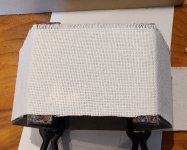
The grille cloth i used for this experiment is quite coarse, i expect to use a finer mesh.
It gives 4mm of top clearance.
The tension of the sock is important, i imagine a velcro strip on each edge, onto the cabinet back, fasten one side and wrap right round adjusting the tension as the second side is fixed.
Does that felt edge look to be a good treatment for the edge diffraction?
With answers to above its about time to order some materials.........
Each driver section will be split from the next by an 8mm mdf divider, the sides will be 12mm mdf, the same as the baffle and rear in the pics. I made them of 19mm today because that was at hand. Then with the same external dimensions this is a 2litre per driver cabinet. i assume this addresses the point made by Freedom above?
Each section will be lined with the same felt as the driver surround.
I have one small problem to consider where the router relieved mounting hole crosses the divider, seen as a part circle on the baffle back in the pictures.
I remember discussions about mounting the drivers on a neoprene or similar to seal well/damp some vibration.
If i do that i must remember to put it under the felt as well to retain the clearance.
The grille cloth i used for this experiment is quite coarse, i expect to use a finer mesh.
It gives 4mm of top clearance.
The tension of the sock is important, i imagine a velcro strip on each edge, onto the cabinet back, fasten one side and wrap right round adjusting the tension as the second side is fixed.
Does that felt edge look to be a good treatment for the edge diffraction?
With answers to above its about time to order some materials.........
Attachments
3mm won’t bend too far…..but enough for a curved side/taper. I use a bunch of ratchet straps with furring strips and blocking to keep even pressure. I secure one end with brads first……takes a little practice…do a dry run and you‘ll understand where to put the strips and blockingI have also looked at that Mayhem, what minimum radius will that achieve?
Its also quite complex imagining how to maintain good contact across the entire inter-laminate surfaces as they glue, and keeping it straight without quite complex construction........
M
The curved side appeals, a tall Sonus Faber look, would look nice at the end, i visualised it in walnut veneer, but then i wont have the sock solution available to me, so currently feeling the Mark 1 will be hexagonal section, made in one length, with dividers at each volume, as per the mock-up. I remind myself of the early comments about work involved and currently don't wish to multiply it up. if one day i get sufficiently bored to need another project i can re-make the cabinets............i remember writing at the beginning this would be a one off project though..........
Hi Mike
Just a maybe crazy idea:
If you live near by the coast, go look at the aluminum masts of sailingboats, like 50+ feet yachts. I once worked at a factory, where we build masts for sailingboats in aluminum and later carbonfiber. Wesayso´s speakers kind of look like a peace of a mast. Sometimes those masts break or need to be replaced, and then you could use a section of that and fill it with dividers to not have an organ pipe! I can´t tell you where to find those things in the UK here in Denmark I would know where to go. Maybe there still are factories int the UK that make masts or local yacht repairshops? The factory I worked at used extruded profiles that where cut to lenth, and then the off-cut went in to the metal-waste-bin.
Good luck
Steffen
Hi again
Now I am at it.
You could use a round PVC tube like a 10" sewer-pipe. Then you have a regular shape to work with, to make a flat driver-mounting surface out of MDF or probably easier 3D print it.
AND you can stil wrap it with cloth as described in post #130
Happy tinkering
Steffen
Now I am at it.
You could use a round PVC tube like a 10" sewer-pipe. Then you have a regular shape to work with, to make a flat driver-mounting surface out of MDF or probably easier 3D print it.
AND you can stil wrap it with cloth as described in post #130
Happy tinkering
Steffen
Hi Steffen, the mast section idea is a very good one, and i am familiar with them, having worked in that industry all my life. However, i cannot DIY materials like carbon and aluminium, so i have developed the idea of the hexagon section.
Round plastic pipe, likewise, i did check this out and could probably work that, but by the time i have cut out the baffle flat etc i see little difference to the route i am going. By the way, the pipe is surprisingly expensive!
I think these are both good ideas, and the appeal will be different for each builder, i don't mind the work involved and am comfortable with carpentry, so that's the route for me.
A bit of a pause now while i gather materials and details.
I am assuming i will crimp terminals to the wires for each drive unit's spade connectors, although i might solder to the connectors
The hexagon shape with round overs sounds very interesting and with the grill sock over it, should be visually appealing.
Is your plan a 5 side glue up with a removable back or baffle as the 6th side?
Building it all six sides glue up and fishing the wiring through the driver holes sounds like a nightmare otherwise. Clamshell would work too……more room to work inside the box and with the sock grill, a slight misalignment won’t be noticed.
I intended to glue up all six and the dividers and make it airtight, add felt lining, run the wiring up the back and through into each chamber with enough spare length on each spur to attach to the driver before that is screwed to the baffle..........is there a problem in that I have not spotted.
My current idea is to cut each angled panel, glue each pair of side pieces to make them one, lay the back on a big flat bench, place and glue on the cell dividers, add the (now one piece) sides and finally the precut baffle. as you say some tolerance will be disguised by the sock. I may biscuit joint some parts, but will see how they look when cut and probably just use a few jig blocks and strips.
However, what is clamshell?
M
A clamshell would be building the hex in two halves and then after wiring and driver install, secure the two halves together with screws and a pocket hole jig from behind. This will allow you easier access to wiring and adjusting enclosure fill without having to remove any drivers.
Kreg makes some great pocket hole tool solutions. After building quite a few 12 unit live sound arrays for friends, i can say with complete confidence that this makes life so much simpler.....i didn't use clamshell but instead a removable baffle or a removable back panel.....these were quadrilats though
Kreg makes some great pocket hole tool solutions. After building quite a few 12 unit live sound arrays for friends, i can say with complete confidence that this makes life so much simpler.....i didn't use clamshell but instead a removable baffle or a removable back panel.....these were quadrilats though
- Home
- Loudspeakers
- Full Range
- Another corner array project