Pedja said:
Jan,
If I understand you, you would go that way if, say, you’ll have to have a sin(x)/x compensation for non-o/s dac (presented curve is almost perfect)? No problems with this?
[snip]Pedja
Don't kow, I have no idea what this has to do with the subject at hand. In fact, I don't know about this sinx/x stuff anyway. I just live by the motto that if you understand opamps and ohms law, you can do anything (almost).
Keep trying.
Jan Didden
Pedja said:Hello Charles,
The problem is that with capacitance going straight from the inverting input we obviously have a resonant circuit. Some resistance taller than 680 Ohms should be used to decouple this.
[snip]
Pedja
Pedja, since you obviously understand this resonant stuff, which elements are there that resonate? I can't find them.
Jan Didden
Eureka
I always bandwidth limit input signals to any amplifier as it makes the design of the subsequent amplifer much easier in terms of stability and all of the oft-talked about distortion mechanisms (like TID etc.).
All of these distortion mechanisms come down to simply a failure of feedback to control the output and this is exacerbated by feeding input signals beyond the capabilities of the amplifier.
The key is doing the input filtering (and it should be done right at the front end of the system) in a way that ensures the cure doesn't become worse than the disease.
Andy.
This is why I believe the LPF has the sonic benefits described by not a few now.
I always bandwidth limit input signals to any amplifier as it makes the design of the subsequent amplifer much easier in terms of stability and all of the oft-talked about distortion mechanisms (like TID etc.).
All of these distortion mechanisms come down to simply a failure of feedback to control the output and this is exacerbated by feeding input signals beyond the capabilities of the amplifier.
The key is doing the input filtering (and it should be done right at the front end of the system) in a way that ensures the cure doesn't become worse than the disease.
Andy.
janneman said:
Don't kow, I have no idea what this has to do with the subject at hand. In fact, I don't know about this sinx/x stuff anyway. I just live by the motto that if you understand opamps and ohms law, you can do anything (almost).
Keep trying.
Jan Didden
You shouldn’t actually. Just believe me, that is the wanted curve. So, yes or no?
(I rather wouldn’t even start to try in this specific case without your explicit approval.)
Pedja
janneman said:Pedja, since you obviously understand this resonant stuff, which elements are there that resonate? I can't find them.
Keep trying.
Pedja
Sorry, no, I am not.
What annoys you? The fact that I just couldn’t (and believe me, I don’t have such plans) to stay silent in situations like this. And I noticed, well Jan, take note on this, for you, it was enough to give me… etiquette (because the politician is not my job).
I noticed your certain contribution here, but your approach here is… no, I’ll not tell you what it is. Try to understand it by yourself.
Please, can you get rid of behavior because of which such places stop to be good places for the audio discussion?
Pedja


Pedja said:Sorry, no, I am not.
What annoys you? The fact that I just couldn’t (and believe me, I don’t have such plans) to stay silent in situations like this. And I noticed, well Jan, take note on this, for you, it was enough to give me… etiquette (because the politician is not my job).
I noticed your certain contribution here, but your approach here is… no, I’ll not tell you what it is. Try to understand it by yourself.
Please, can you get rid of behavior because of which such places stop to be good places for the audio discussion?
Pedja
Well, I just asked you which elements were resonating. Since you stated that it was "obvious" I thought you could just tell me, since I couln't find them as I said. Your response was "keep looking". That reminded me of politicians who are often required to state something convincingly of which they have no clue.
Jan Didden
janneman said:
Well, I just asked you which elements were resonating. Since you stated that it was "obvious" I thought you could just tell me, since I couln't find them as I said. Your response was "keep looking". That reminded me of politicians who are often required to state something convincingly of which they have no clue.
Jan Didden
My vision is pretty blurred to it seems as I can't see it either.
Did you?janneman said:Well, I just asked you which elements were resonating.
OK, writing the original post I had the intention to put that question by myself, because I am not sure about this. Explained as you have explained, the thing should look the same with different opamps, just having bigger peak with the higher bandwidth opamp. In fact it doesn’t look exactly that way. LM1875 (shown previously) is 5MHz unity gain opamp. OPA2604 (first diagram here; take note that Y scale is 40dB now, was 30dB) is 20MHz (take note also that the frequency of the peak is somewhat lower that in the case of LM1875). AD825 (40MHz, the second diagram) doesn’t have any peak, and LM6172 (third diagram) which is topologically a CFB with buffered negative input is 100MHz and has a nice roll-off, almost as we would like to have and not to use the buffer.
Pedja
Attachments
Pedja,
Resonance is the periodic exchange of energy between an inductive and a capacitive part. That is not the case here at all. There is no resonance anywhere here. The peak in the response comes from an increase in gain as the feedback factor diminishes at higher frequencies.
I got irritated by your sweeping statement "it is obvious bla bla resonate". If, as you now say, you were not sure, don't say it. People here want to learn, not to be put on the wrong foot.
Lets forget it now, OK? It's hot here and I don't want to draw this out.
Have a nice day,
Jan Didden
Jan,
I don’t have really any interest to proceed with this, but now real irritation came from your side.
Would you tell me please why did I post the previous post, including the screenshots? As you can see, your explanation simply fails here.
I am not sure where the inductance that matters is. That is what “I am not sure”. To find this, concrete schematics of the certain opamps should be discussed.
You talk about the increase in gain in high frequencies. OK, that frequency is determined by the given shunt cap and what impedance? Where is that in the case of LM6172?
Jan, please, read the posts you are answering to.
Pedja
janneman said:Resonance is the periodic exchange of energy between an inductive and a capacitive part. That is not the case here at all. There is no resonance anywhere here. The peak in the response comes from an increase in gain as the feedback factor diminishes at higher frequencies.
[/B]
Hi, Jan
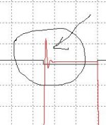
From somewhere :"Ringing and overshoot are the first signs of instability, and oscillation is the final sign, ..... "
There is no discrete reactive elements around, but something is ringing, like bells......
")
This Pedja's picture show some resonance..IMHO
I saw this on my scope today too (network 10k-6n8-680R-220kFB)
Overshoot was on ca 23kHz with only 2dB (LM3875)
Regards
Attachments
moamps said:
Hi, Jan
From somewhere :"Ringing and overshoot are the first signs of instability, and oscillation is the final sign, ..... "
There is no discrete reactive elements around, but something is ringing, like bells......
This Pedja's picture show some resonance..IMHO
I saw this on my scope today too (network 10k-6n8-680R-220kFB)
Overshoot was on ca 23kHz with only 2dB (LM3875)
Regards
A peak in the response? A resonance? A bit of both? I notice the undershoot after the peak, that looks like the start of an oscillation? Horror! Quickly damped though, so still looks stable. Nice screen shots.
This argument seems to be a bit of a dead end. Clearly about something that doesn't work with LM18xx and LM38xx. Certainly not as intended. So if something doesn't work, you discard it and get on with it.
Re unnecessary arguments, this reminds me...
Confucius say: "He who throws mud loses ground."

Joe R.
Pedja said:
Did you?
OK, writing the original post I had the intention to put that question by myself, because I am not sure about this. Explained as you have explained, the thing should look the same with different opamps, just having bigger peak with the higher bandwidth opamp. In fact it doesn’t look exactly that way. LM1875 (shown previously) is 5MHz unity gain opamp. OPA2604 (first diagram here; take note that Y scale is 40dB now, was 30dB) is 20MHz (take note also that the frequency of the peak is somewhat lower that in the case of LM1875). AD825 (40MHz, the second diagram) doesn’t have any peak, and LM6172 (third diagram) which is topologically a CFB with buffered negative input is 100MHz and has a nice roll-off, almost as we would like to have and not to use the buffer.
Pedja
Without promoting too much further discussion, these screen shots got me thinking. So I quickly did simulate in CircuitMaker using an ideal IC and transposed 10K and 680R. I measured the RMS voltage @ 1KHz and 20Khz, before and after swapping 10K and 680R. They were identical. So in theory, using an ideal IC, but theory and practice are different things.
Ergo, the LM18xx is not an ideal IC. Surprise, Surprise!
So I would go along with your screen shots.
Joe R.
Hi Joe,
I checked a few chips more using the same circuit and haven’t had success. It is shown behavior of chips without the shunt cap and with 68pF, 680pF, 6.8nF and 68nF caps.
Note that the OPA chips (having shorter bandwidth) set to gain of 20 anyway have roll-off inside the audio band.
Pedja
I checked a few chips more using the same circuit and haven’t had success. It is shown behavior of chips without the shunt cap and with 68pF, 680pF, 6.8nF and 68nF caps.
Note that the OPA chips (having shorter bandwidth) set to gain of 20 anyway have roll-off inside the audio band.
Pedja
Attachments
AuroraB said:Without looking into this matter in greater detail, as I am on vacation and "just happened" to pass by a PC,- have you all forgotten your filter theory??
The peaked responses shown are all typical examples of Q> appx 2, and/or a seriously misterminated filter.....
Hi,
Had you looked into the matter in greater detail, you would have noticed that this circuit is an interesting example of how to get such a response (Q=2 or so) with only one reactive element (C) by simply pushing a chip beyond its frequency and phase limits (or intended use). Impracticable as it may be...
Regards
- Status
- This old topic is closed. If you want to reopen this topic, contact a moderator using the "Report Post" button.
- Home
- Amplifiers
- Chip Amps
- Another buffer conversion