Ok you guys are right, I changed the pathlength to 1 cm and the low end looks close enough to the same to conclude there is no benefit to the waveguide below 40 hz or so. This had me confused for a bit because winisd shows an entirely different graph with the same sealed box of 100 cubic feet and the same 8 drivers. Winisd says it rolls off hard at 35 hz and is only capable of 112 db at 10 hz, as opposed to about 135 predicted by hornresp. Not sure how to change to .5 x pi in winisd, but even so, the difference in the graphs produced by these 2 programs don't have anything in common.
Back to the drawing board.
Back to the drawing board.
Greets!
Don't have time to ponder all the imponderables, but I was curious what Prof. Leach had to say about the basic design using the Tempest-X, so here's a single semi-optimum (within HR's max mouth limitation) 10-61.67 Hz hyperbolic horn truncated for eight woofers and 0.5 pi space driven with 3200 W total to reach Xmax/10 Hz:
GM
PS: If you wire eight 4 ohm drivers in parallel the amp load approaches DC, so wire them four each series/parallel to remain at a nominal 4 ohms. Also I just noticed the published specs I used are different from yours..........
Attachments
You're welcome!
Unfortunately I forgot to update Vtc/Atc for eight drivers.........
Anyway, you can reduce its size quite a bit due to room gain without compromising SQ due to room gain if the sims are to be believed, but this is your 'dream' project, so I'll let you work through it as it's a good educational project requiring designing the room around the horn to work as a single closed system for best performance.")
GM
Unfortunately I forgot to update Vtc/Atc for eight drivers.........
Anyway, you can reduce its size quite a bit due to room gain without compromising SQ due to room gain if the sims are to be believed, but this is your 'dream' project, so I'll let you work through it as it's a good educational project requiring designing the room around the horn to work as a single closed system for best performance.
GM
Attachments
Thanks again for all the help guys. I've played a bit more and this an awesome crash course for me on hornresp and big horn design, so cheers for that.
Quick update - I'm quite surprised that these big horns are so tolerant of changes in some areas like the back chamber. Making the back chamber MASSIVE (10000 liters - more than 2x GM's rear chamber model size) doesn't do much to response except gently roll off the very low end (to fit the room gain a bit better), so the size of the big sealed box can be made to "fit" the design fairly easily, it's size is incredibly flexible without causing big changes in response.
The shape I drew in post 1 (especially at the size I had in mind) will not be possible as a sub bass horn. Tractrix is the only flare that comes even close to a fast enough expansion at the final flare to match the picture, but using such a drastic tractrix flare pulls the lower cutoff of the horn action up to about 30 hz. To get a lower horn cutoff it needs to flare less. I haven't found a way to use a rapid flare AND make to low tuned as well yet. This means it would be almost freakishly simple to design this exactly according to the drawing, including the overall original small design, but it would only be a 40 hz horn. One benefit of the tractrix curve though, is that it seems to allow for quite short pathlengths (easier to integrate into the shape in the drawing), although the overall size remains similar.
So I can make it low tuned (flat to 10 hz) but it needs to be massive and the flare profile doesn't fit the picture (instead of a gently curved front wall it would look more like a large ship hull crashed into the front wall of the room).
Or I can make it a 40 hz and up horn and follow the picture almost exactly, but the tempestx is probably not the best driver for this job, and not sure a 4000 liter horn (the size I originally pictured in my mind) is necessary for 40 hz and up.
This is fun, thanks again for all the help everyone.
Not sure, I havent' had a chance to play lately.
Hornresp lets me choose the flare angle OR the horn cutoff OR the length. I'd like to choose the flare angle AND the horn cutoff, and let it calculate length, but I can't seem to do that.
Either way, it's not too important. If it doesn't work, it just doesn't work. I don't want to try to force physics into the shape of a picture I drew.
just a guy said:Hornresp lets me choose the flare angle OR the horn cutoff OR the length. I'd like to choose the flare angle AND the horn cutoff, and let it calculate length, but I can't seem to do that.
Hi just a guy,
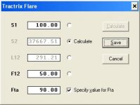
I assume that you are using the Tractrix Flare Horn Segment Wizard? If so, simply select the "S2 Calculate" option and then click on the Fta check box. The mouth area and axial length can then be calculated given the throat area, cutoff frequency and flare tangent angle.
Hope this helps.
Kind regards,
David
Attachments
Hi David, I've only had a couple hours of time to play with this great little program so far, so I have lots to learn yet.
I'll try your suggestion when I am able.
I've had flu the last couple of days but it's almost better so I'll have more time to play soon. Thanks for your help.
I'll try your suggestion when I am able.
I've had flu the last couple of days but it's almost better so I'll have more time to play soon. Thanks for your help.
Hi Guy,
Your project looks like fun. As I pondered your project, I began to realise that it isn't too unlike my speakers that I am just now finishing up. I used 2 18s on each side and they face forward into the room rather than backward into the wall, but my horns exit in the front corners of the room and the side and front walls become functionally part of the horn mouth. I left room on my speaker baffle board to add two more drivers on each side which be nice. I did make the cabinets out of concrete which I think is a good thing.
I like the organic design of your horns. Mine are rather boxy and square.
It works though. I get smooth, phenominal bass right down to 16 Hz. Movies take on a whole different feel and music sounds so nice with that extra octave on the bottom. You can see some photos of my speakers on my blog.
Hi Graydon, nice work.
How did you model them?
my horns exit in the front corners of the room and the side and front walls become functionally part of the horn mouth.
How did you model them?
I finally got some more time to play with hornresp and this is what I noticed.
1. To make the smoothly curved front wall that I drew the fta (flare angle) needs to be as close to 90 degrees as possible. Even 70 degrees could be acceptable, but the curve is not as smooth and by the time you get down to about 40 degrees it starts to look like the hull of a ship crashed through the front wall of the room, as I mentioned earlier.
2. AFAIK tractrix is the only flare that can give a huge 90 degree flare at the end. From what I`ve read tractrix is no good for bass but hornresp seems to disagree somewhat.
3. I haven't tried really hard yet, but when I did try I was not able to fit a tractrix segment as the final flare to any other previous segments, regardless of flare type. So I simply modelled using a single segment tractrix flare. Makes everything pretty easy anyway.
4. I still can't get the flare angle AND F12 (lower horn cutoff) that I want with any combination of the other parameters. I can make a horn with a 90 degree flare but the F12 will only be 30 hz. To get the F12 lower, I need to use less horn flare. At 70 degrees (IIRC) I can get the F12 down to about 25 hz, and with a 10 hz F12 the flare angle is less than 20 degrees. Regardless of the other inputs I can't get a 90 degree flare AND a 10 hz F12. I think the mouth size might be the limit here. I've tried adjusting every other input parameter up and down. The only thing I can't do is make the mouth bigger, and I think this is imposing the restriction I'm stuck on.
5. Maybe I'm really dense (actually I'm PROBABLY really dense) but GM's models use 4 series x (not +) 4 parallel drivers, which seems to add up to 16 drivers. I only want to use 8. So I started modelling with 8 drivers in parallel again. It does change the response, but at least I know I`m modelling the correct amount of drivers.
6. As GM mentioned, there are a whole bunch of imponderables here. I still don`t think that what I am modelling is what I drew. I think the entire room would need to be modelled in akabak to get a real idea of what would really happen. I`m not sure the room is big enough to allow a horn of that size to breathe properly. In car audio I`ve heard that the sub box should occupy no more than 15 percent of the available volume, and the horn I drew is way more than 15 percent of the room.
Overall it was a nice picture and a nice idea but I am not nearly smart enough to even guess at what is going on with any accuracy. To complicate things further, I`m not sure what type of wave propagation would occur. AFAIK by definition this will not produce planar or even real line array behavior, but OTOH, it would seem that it actually would produce a single wall to wall, floor to ceiling wavefront, which is what a planar wave is. Either way, at this point, it`s clear I have no idea what I`m even talking about anymore.
I`m seriously wondering if it might be almost as good to just take the same 8 drivers and mount them in IB, firing up through the floor directly underneath the listening position. Certainly would be lots easier. I would certainly lose lots of peak spl potential, but I`m not really sure I need 140+ db peaks anyway.
i made a script to approximate the behaviour of a horn in a room. the room is simulated as a duct element, so it has standing waves etc. should be exact enough for subwoofer simulation. it assumes the horn mouth is at one wall of the room. for exact placement, the script needs more elements (waveguides). it simulates the response at the mouth.
Copy the script into an empty akabak script and hit F5 to simulate. You can easily change the driver, horn and room to your own specs. the QD/fo value simulates the damping of soundwaves in the room. Small value = high damping. You have to experiment with this value, as i have no clue what value a normal room would have. with values greater than 1, you can see all those standing waves
Def_Driver 'Dr1'
Sd=466cm2
fs=18.1Hz
Qes=0.21
Qms=3.7
Vas=139L
Re=3.5ohm
Le=4.2mH
system 'S1'
Driver Def='Dr1' Node=1=0=10=11
Enclosure 'E1' Node=11 Vb=100L
Waveguide 'H1' Node=10=20 STh=300cm2 SMo=20000cm2 Vf=30L Len=5m T=1
Duct 'Room' Node=20=21 WD=400cm HD=250cm Len=500cm QD/fo=0.1
Radiator 'Mouth' Def='H1' Node=20
Thanks for that Mavo. I've heard how tricky akabak is and as a result I've never downloaded it or even looked at it. I guess this is a pretty good reason to give it a go. I'll have to study a bit to find out what your script even means, much less change it to suit my needs at this point.
I was thinking of something like this awhile back using floor to ceiling sonotubes. You could also open up the ceiling and/or the floor for IB speaker response. I hope this image comes through.
An externally hosted image should be here but it was not working when we last tested it.
just a guy said:Hi Graydon, nice work.
How did you model them?
Thanks. I tried modelling it in WinISD, Hornresp and a couple others. They gave results which were similar in some areas but divergent in others. I tried it sealed, ported and with the exponential horns. I designed the cabinets such that I could switch from one to another fairly easily. That way I could try it with real sound and hear the results with my own ears. The sealed cab sounded good. It was smooth but low extension wasn't too fantastic. The ported trial showed promise. Then I physically modelled up the horn with a couple sheets of plywood on the floor and built the horn shape with blocks of 2x12. I had trouble testing it because the plywood horn moved enormously when I cranked it up. However, with a few people standing on it to stabilize it, I finally got some rough numbers and despite the leaks, and the flexing in the plywood horn model, the horn's output was pretty substantial so I decided it was worth trying. I then built the horns out of concrete using the horn shapes that came about from modelling in Hornresp. That model was fairly simple to build and pretty close to what I actually had to work with. I tuned the horn to 18Hz and although it doesn't seem to be terribly efficient, it does have a small peak at 18Hz. I wish I could do a full length horn. Maybe next time.
- Status
- This old topic is closed. If you want to reopen this topic, contact a moderator using the "Report Post" button.
- Home
- Loudspeakers
- Subwoofers
- Another big horn dream... comments and concerns?