hi, i have mostly fiddled around one chip classd solutions and bought broken nx3000 to repair and learn a bit. so sorry if this is a bit newb question.
classic protect fault, one output fet shorted(gate short) bought some SUP90100E fets to replace original IRFB4227 as there is half RdsON and bit higher current rating, lower Qg, and i thought that was bit too easy.
fast forward to when parts arrived and replaced, amp turned on worked for 10 seconds or so, and blown another fet again, but this time it was not shorted gate but drain source short.
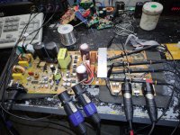
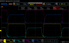
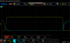
i put one of old 3 fets in place to get some scope shots from gate outputs after i checked all zeners and diodes in drive circuit, i turn amp on just few seconds wait only for scope to get data and turn it off so i can see what is going on.
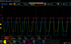
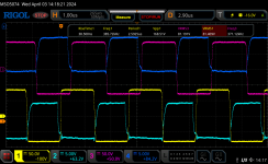
attached is picture of all 4 gates, low side is correct at +-10ish Volts, but high side has gate swinging +-80V or full rail voltages, i cant wrap my head around how is this possible and already done all i can so i post here for someone smarter to point me in right direction.
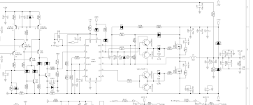
amp is half bridge, and gate driver ic is IRS20957S with some i think its called totem pole pnp npn transistors. croped schematics also attached.
thank you and have a nice day.
classic protect fault, one output fet shorted(gate short) bought some SUP90100E fets to replace original IRFB4227 as there is half RdsON and bit higher current rating, lower Qg, and i thought that was bit too easy.
fast forward to when parts arrived and replaced, amp turned on worked for 10 seconds or so, and blown another fet again, but this time it was not shorted gate but drain source short.
i put one of old 3 fets in place to get some scope shots from gate outputs after i checked all zeners and diodes in drive circuit, i turn amp on just few seconds wait only for scope to get data and turn it off so i can see what is going on.
attached is picture of all 4 gates, low side is correct at +-10ish Volts, but high side has gate swinging +-80V or full rail voltages, i cant wrap my head around how is this possible and already done all i can so i post here for someone smarter to point me in right direction.
amp is half bridge, and gate driver ic is IRS20957S with some i think its called totem pole pnp npn transistors. croped schematics also attached.
thank you and have a nice day.
Attachments
Current limit the supply bus voltage by doing so you can probe the circuit the problem could be anywhere. You could try to force a pwm signal and check if the drive circuit is operating correctly, initially could be a faulty buffer driver or defective ic or both. Interesting they using a discrete comparator.
sadly both smps and amp are on same pcb and is not possible to remove connection from psu, today i tested a bit more, im curious if everything is actualy ok and i simply put wrong mosfets by ignoring some specifications(rise time).
i measured wattage after amplifier startup it rises steady from 20ish Watts to 100+W after 10 seconds when i disconected it(did not burn but heatsink got warm very fast), also i found rise time in datasheet of original transistor is 20nS while for this replacement is 50nS, but on scope from gate to gnd it says 28ns rise time but is that measuring just gate drive circuit or should this only be appearent if i had a probe to measure gate-source or gate-drain im not sure? and also speaker output is referenced to ground so i get same voltages on gate with scope a+b.
if rise time is problem could i swap those delay set resistors on gate driver ic to give 30ns more delay? if that works im ok if that will limit amplifier effective power output and buying just 1 new mosfet. will that also change oscilation frequency?
thank you for your time and knowledge..
indeed that done the trick, i have removed resistor to v+ from dt pin, and left one that goes to gnd, datasheet states less than 10k for longest setting left original 3k9 should be ok, now consumes 30w in idle stable, heatsink still too warm without fan, tested to clipping on 8 ohm speakers, sound quality is good on test speakers.. when i buy original fets i will still leave out this resistor as there is plenty power and this should make amp more stable?
thank you people.
thank you people.
Attachments
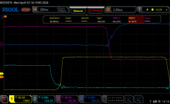
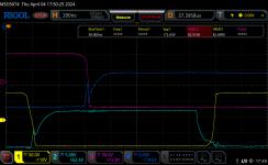
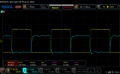
freq is bit lower now, but rise time longer not sure if that is ok or i misunderstood something and thought it would be same but with more space between pulses as that delay is set to more time, there is some ringing or what is called now that was not appearent before, is this problem with wrong fets or with some other circutry? any good app notes for this stuff where i can read more about it?
Attachments
Good spot on delay times and the possibility of cross conduction.
The following may be wrong but self oscillating amplifiers rely on the loop being unstable with >180 degrees of phase shift at crossover. The LC output filter almost gives you this and then they get tipped over the edge. Part of that tipping comes from delays in the circuit so having introduced an additional delay you might expect that the self oscillating frequency would go down.
In and of itself that should not cause a loop stability problem. You just lose loop bandwidth and I doubt the changes you have made would hurt things much over and above component tolerances present in the original circuit.
In terms of the ringing you are seeing I'm sure you are not concerned about it causing stability issues.
During Mosfet turn on you are seeing a plateau, reversal, in the gate drive voltage as the drain of the device shoots off to lots of volts and overcomes the gate drive through the Drain Gate capacitance. You can see this one on your Mosfet data sheet.
https://www.vishay.com/docs/63034/sup90100e.pdf

The opposite one to that is during turn off where you see a similar plateau, slow beginning of Vds rise, before the device properly turns off and then the ringing in your gate drive waveform is likely due to device parasitics.
The only components you have on board that might affect that are the series RC networks, 100p/15R across the Drain-Source of the devices and, assuming adjusting them might clean things up or improve losses, your best guess might be to change the values of the 15R resistors.
I have no idea whether it would work or how to make the guess. It is possible that the original was messed about with to find a sweet spot but it might be tied into at best...
SUP90100E

IIRFB4227

The SUP device does not appear to give lead inductance information but you might assume it is the same as that for the IRF device. The only big change is Crss which has been reduced from 91p to 12p or about a factor of 7.5. Being resonant circuits these things operate on square roots so that is 2.75 and my wet finger, assuming the impedance has gone up, therefore says that if you increase the 15R resistors to 39/43R you might see a, hopefully better, difference.
The following may be wrong but self oscillating amplifiers rely on the loop being unstable with >180 degrees of phase shift at crossover. The LC output filter almost gives you this and then they get tipped over the edge. Part of that tipping comes from delays in the circuit so having introduced an additional delay you might expect that the self oscillating frequency would go down.
In and of itself that should not cause a loop stability problem. You just lose loop bandwidth and I doubt the changes you have made would hurt things much over and above component tolerances present in the original circuit.
In terms of the ringing you are seeing I'm sure you are not concerned about it causing stability issues.
During Mosfet turn on you are seeing a plateau, reversal, in the gate drive voltage as the drain of the device shoots off to lots of volts and overcomes the gate drive through the Drain Gate capacitance. You can see this one on your Mosfet data sheet.
https://www.vishay.com/docs/63034/sup90100e.pdf
The opposite one to that is during turn off where you see a similar plateau, slow beginning of Vds rise, before the device properly turns off and then the ringing in your gate drive waveform is likely due to device parasitics.
The only components you have on board that might affect that are the series RC networks, 100p/15R across the Drain-Source of the devices and, assuming adjusting them might clean things up or improve losses, your best guess might be to change the values of the 15R resistors.
I have no idea whether it would work or how to make the guess. It is possible that the original was messed about with to find a sweet spot but it might be tied into at best...
SUP90100E
IIRFB4227
The SUP device does not appear to give lead inductance information but you might assume it is the same as that for the IRF device. The only big change is Crss which has been reduced from 91p to 12p or about a factor of 7.5. Being resonant circuits these things operate on square roots so that is 2.75 and my wet finger, assuming the impedance has gone up, therefore says that if you increase the 15R resistors to 39/43R you might see a, hopefully better, difference.

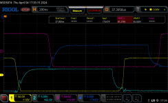
scratch that already done, also forgot to add that i fiddled around a bit and both high side are SUP and both low side are IRFB fets.
only had 0805 resistors of 39R, but this is all temporary and for learning so why not.
also sorry for not mentioning pink and yellow trace are high side.
need to sleep a bit on this informations.
not sure there is difference but only changed r from rc on high side where SUP fets are, if i understood you correctly.
also not sure if it is thermal paste and isolating pads set bit better after few cycles of heating but from touch perspective heatsink without fan seems a bit colder now with those 39R resistors in place, also tried different scope mode some "peak" thing looks more noisy, so volts measuring got bugged and it detected kilovolts somehow and triggering did not work right.
should have put SUP on one channel and IRFB on second but now is bit late, will order IRFB anyway so im afraid of removing pads as pcb needs a lot of heat and it already survived few resolderings.
edit: now i see on pictures i mixed up and swaped irfb rc instead, definetly need sleep.
Attachments
![2024-04-03-21-34-11-682[1].png](/community/data/attachments/1202/1202501-83e267c89a82901c64aec25328437fbf.jpg)
While the success of the outcome remains uncertain, the educational benefit derived from the experience is substantial, facilitated by practical lessons.
The adjustment of the "idle self oscillating parameters" has led to a modification in the observed switching frequency (fsw) reduction. Consequently, This is due to updated propagation delay at the switch(es) as a aggregate of the following components: Propagation Delay (Pd) at the "controller + switches" equals the sum of the Mosfet's rise and fall time, deadtime (Dt), and the gate resistance during turn-on and turn-off (Rg).
Hence the drop in lower idle frequency, longer deadtime will affect/increase THD but will result in lower loss leading to cooler switches at idle.
Lower Fsw will alter control loop transfer function under dynamic conditions.
Last edited:
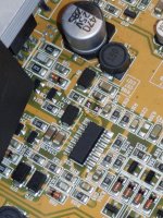
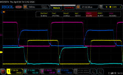
finaly done correct swap of R from RC part from drain to source to correct fets, SUP is low side IRFB is high side, made a mistake before, on low side its now 100pF original and 39R swaped.
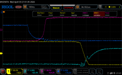
blue traces are low side.
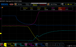
also done some measurments while playing music on mid level, with wider width pulses when music is playing that plateau or reversal seems to reach higher levels that follow high side exactly until drop and finaly rise, see last two pictures, that worries me.
there also seem to be some psu crosstalk/distortion of sort from 1 channel to another also seen on last two photos looks like small oscillation that is present on different places but always same time on both low side fets, right around time where fets cross over.
not realy sure if anything changed, but after reading around a bit and thinking next thing i will try tomorow is change 1uF capacitor, one that is parallel with zener so in that way try to make rise time of low side fet bit slower, also i might first try with higher voltage x7r 1uF cap as this is ceramic cap rated at 16V according to schematics and maybe there could be some ringing from capacitor also? later will try lower value cap.
was playing music all afternoon from this with fan attached after heatsink temps started rising and in same time idle no music consumption rised with temperature, +2 or so W only but it droped down after fan cooled it a bit after few minutes.
this amp actualy sounds good, bit dark when compared to classAB on same speakers but may be because of more power available and better damping factor so more low freq content is very appearent.
cheers and thanks for lots of information.
blue traces are low side.
also done some measurments while playing music on mid level, with wider width pulses when music is playing that plateau or reversal seems to reach higher levels that follow high side exactly until drop and finaly rise, see last two pictures, that worries me.
there also seem to be some psu crosstalk/distortion of sort from 1 channel to another also seen on last two photos looks like small oscillation that is present on different places but always same time on both low side fets, right around time where fets cross over.
not realy sure if anything changed, but after reading around a bit and thinking next thing i will try tomorow is change 1uF capacitor, one that is parallel with zener so in that way try to make rise time of low side fet bit slower, also i might first try with higher voltage x7r 1uF cap as this is ceramic cap rated at 16V according to schematics and maybe there could be some ringing from capacitor also? later will try lower value cap.
was playing music all afternoon from this with fan attached after heatsink temps started rising and in same time idle no music consumption rised with temperature, +2 or so W only but it droped down after fan cooled it a bit after few minutes.
this amp actualy sounds good, bit dark when compared to classAB on same speakers but may be because of more power available and better damping factor so more low freq content is very appearent.
cheers and thanks for lots of information.
Attachments
didnt do that, not sure what and how right now, returned original parts in rc network might leave it as is and instead try to diy something with irs chip and with 75v fets i have plenty in stock. in meantime i pulled my nx6000 apart and measured gates, either nx6000 is also not ok or this is "normal" behaviour of this amps as nx6 is just same but two nx3 bridged on same pcb. this is no load no output measuring and that cross conduction part is looking worse without than in this nx3000 with signal output. this one is working on around 300khz. will do same mod with removing resistor at irs to get bit more time between pulses as on nx3. also idle watts from wall are exactly double.
cheers.
cheers.
Attachments
- Home
- Amplifiers
- Class D
- Another Behringer NX3000 repair