Hi All, Now that I know Dragance007 wants 2 of them, I will now Give away the remaining 2 boards to one other person, ALSO TOTALLY FREE.
To All Persons Interested in these FREE PCB's,
Pick a number between 1 and 100 and Post it Here.
The Person Closest to a number that I have Picked will get these boards. I will wait a few weeks to give everyone a chance at winning these PCB's.
The Results will be posted here.
Take care...........Gary
I Just made a PCB for the DC Protection Circuit.
I Assume it is Correct to the Schematic.
Please Check it Over.
If I can get some Feedback on it, I will include one of these to both the Winner and Dragance007.
http://www3.telus.net/chemelec/Projects/Misc-PCB/
Take care...........Gary
I Assume it is Correct to the Schematic.
Please Check it Over.
If I can get some Feedback on it, I will include one of these to both the Winner and Dragance007.
http://www3.telus.net/chemelec/Projects/Misc-PCB/
Take care...........Gary
how about 56???
is that your number????
i build this amp(only one chanel), but it's NOT working....
i'm sure that i made a mistake somewhere, but I don't know where ...
this is the problem:
the board is geting hot,not the components,and i have a dc voltage at the exit ....
That is it because the final transistors some stand open, and others completely closed...
And T8, and T9 are the same... Mj31530( the voltage on C-E is 1.6V) is completely opened, and mje15031( the voltage on C-E is 60V) closed
the rails are +- 35V, in the future i will put it to +- 60(i hope it works at this voltage)
the led does light up and T2 and R15 are geting very hot ...
If I pul out the curent limiting resistors then smock comes out of the R15, and T2 is breaken
What could be the problem...
all transistors are ok,i am sure of that
Hi csl113, If you have a high DC output, that is probably causing T2 and R15 to get Hot. It is a result of an error somewhere else. I doubt T2 and R15 are causing the real problem.
<QUOTE>And T8, and T9 are the same... Mj31530( the voltage on C-E is 1.6V) is completely opened, and mje15031( the voltage on C-E is 60V) closed</QUOTE>
What is an Mj31530?
Don't you mean an MJE15030?
But Either you have a Transistor in Backwards or you have a Short Somewhere.
Check all the other transistors for Collector to Emitter Voltages, mabe also Base to Emitter Voltages.
I Haven't built ths Amp, Only because I have a good amp and Don't need this kind of HIGH Power.
Take care.........Gary
chemelec said:I Just made a PCB for the DC Protection Circuit.
I Assume it is Correct to the Schematic.
Please Check it Over.
If I can get some Feedback on it, I will include one of these to both the Winner and Dragance007.
http://www3.telus.net/chemelec/Projects/Misc-PCB/
Take care...........Gary
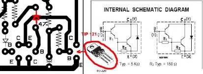
about this:
http://www3.telus.net/chemelec/Projects/Misc-PCB/M-250-DC-Protect.png
i have 2 questions:
1. the diode, is this how you put it, or it was the other way..???
2. TIP121, it's footprint is not CBE, but BCE....,so please change the pcb, to include that...(you could leave it as it is, but it is very dificult to put it in corect position...)
(i thing you will better understand what am i saying in the picture below...)
(i can't write in english , i cand read, ant talk, but i can't write, so,please exscuse my mistakes...)
Attachments
To csl113, The DC Protect Board is Now Corrected for both the Transistor layout as well as the Diode and I also had the 330uf Cap in Backwards.
However the Free board I give away will be the Previous layout.
It Shouldn't be too much of a Problem to fit the Transistor on.
Take care.........Gary
However the Free board I give away will be the Previous layout.
It Shouldn't be too much of a Problem to fit the Transistor on.
Take care.........Gary
no, it Shouldn't....
and, yes, now it's corect...
i also finaly found the error on my amp....
a route on my pcb was faulty ..(not visible with naked eyes, but visible on the multimeter)
now it's working, but i have a difficult time on setting the bias...
how exacly should i set it????
i tried to put a 1,8 mA as shown in the schematic, but the idle curent blow a 2A fuse....clearly that way it's no good...
so i set the idle curent to aproximatly 75 mA/transistor(0.025mV drop across the 0.33 ohm resistors) , this is 1.831-1.836 mA(i can't remembre exacly) on the schematic(colector of T3) if i set it to 50mA/transistor, this vould be a 1.838-1.840 mA on the colector of T3....
so...
how many mA shoul i set it to???,or what voltage drop should i have on the 0.33 ohm resistors..???
and another thing...i can't find the D5,6,9,10...
i have BYV32-100 diodes, and BY228PH , can't i put those instead..???
I Can Supply D5 and D6, The 1N4937's are High Speed Diodes Cost $3.00 US Funds, Including the Postage Cost.
As To D9 and D10, I Don't have any Spec on that, But I would recommend any power diode rated at 100 volts or more, and 2 amps Absolute Minimum.
Since I haven Built the amp, I won't Comment on the Bias.
Quite Sure Dragance007 can help you Better.
Take care........Gary
As To D9 and D10, I Don't have any Spec on that, But I would recommend any power diode rated at 100 volts or more, and 2 amps Absolute Minimum.
Since I haven Built the amp, I won't Comment on the Bias.
Quite Sure Dragance007 can help you Better.
Take care........Gary
Since i did not build this amp in the original till now (not finish yet) i don't now witch bias current is minimum. Further...i used elements not in the original to schematic...lower power supply, 2 pairs of output transistors, almost all differrent transistors... so i had to monitor bias current for about one hour to determine the floating caused by heating up at full power at maximum ambient temperature...and it is now set about 30mA per device.
when i finish the original amp i will have to do it again...it is safe way to set the bias
when i finish the original amp i will have to do it again...it is safe way to set the bias
ok, so i will try at 30-50mA, 75, is probably toooooo much
naw, yet another question...
what voltage is the maximum input(peak voltage), before it goes clipping..???
(this is probably a stupid question, BUT i don't have a osciloscope to test it..not yet anyway,because i will test it on a osciloscope, at a friend, but naw he-s gone for 1-2 weeks...)
and could i use it at + - 60V rails...or is it too much...???
i will need to build 3 more, and bridge them ,so i will have a 500W/8 ohm amp that will drive my 800W/8 ohm MAG speakers....
(at first i wanted to build a leach amp,but 400 ohm, just it was to little(i am hoping to pull almost 550W/8ohm at 60V) from this amp...)
a 1.5 kW transformer is enough, or should i use a 1.8 or a 2 kW...???
Personally I would be looking for a New Set of Ear Drums.
A Full Piece Orchestra Produces 1/3 of One Watt.
Suggest you get More Efficient Speakers.
As to The Supply Voltage, I would keep it at the 55 Volts.
Are you Using All the Origional Transistors as Per the Schematic?
If you are, The Bias Current should be correct with the 1.8 mA. current flow. On my PCB Design, I put a Jumper at that point so a milliamp meter could be easily inserted.
Without the 55 Volt Supply, the Clipping point will Change. But I think it is supposed to be 1.5 volts in for full output.
Don't Quote me on this for sure!
Additionally I would Suspect that the "Green" LED is Important.
Hopefully you used a Green One.
Red and Yellow and Green LED's All have Different Voltages.
This amp design reminds me of my PA amp designs of the 70's except that I used 1K for R1 for a 160KHz input filter to minimise stray pickup on the lines. Also I slowed the turnon of T4 with a long time constant RC to the base eliminating the need for a dethump relay at the output. And CFTriples.
For a Hi Fi amp I'd suggest a better compensation than the 100pF miller slug on T5, rather just define the pole with 10p and use around 33pF from T5 collector to base T2 - a much lighter load on the VAS. High Frequency THD should drop.
The protection circuit would benefit from a suitable R between the two diodes and small electrolytics across the protection transistors. Recalculate the R and 12K's to give better SOAR/load tracking. BETTER STILL remove the protection circuit so it can't cause spurious distortions as they partially turn on and load the VAS on highly reactive loads.
Getting carried away....A cascode of the first stage collector should greatly improve PSRR as will a cascode or 2tr CCS, and the input CMRR.
Suggest you get More Efficient Speakers.
the MAG's are at 97dB@1W......

(i build them myself...)
could NOT find the 715 ohm resistors, so, i put a 750 ohm resistor in place, and the 27ohm resistors are aproximatly 30 ohm.....porhaps that is why i don't get a 1.8 mA...
also my rails are now at 35V...perhaps this why it's not corect...
yes am using original transistors...(i think)
the led is green, but it is a transparent one..i will try with a "normal" one...
For a Hi Fi amp I'd suggest a better compensation than the 100pF miller slug on T5, rather just define the pole with 10p and use around 33pF from T5 collector to base T2 - a much lighter load on the VAS. High Frequency THD should drop.
whem i find a osciloscope i will try it, and see what it hapends....
Getting carried away....A cascode of the first stage collector should greatly improve PSRR as will a cascode or 2tr CCS, and the input CMRR.

you lost me there....
Sorry CS,
The main point of power supply borne crap from the -ve supply intruding is the Vas input and this is improved dramatically by raising the collector impedance of the first stage. Also raising the tail impedance using the std 2 transistor will improve CMRR and PSRR from the +ve supply.
The more impervious you make the amplifier proper to power supply vagaries the less critical it's performance.
With a bit of attention to this you can happily run two channels from the same unreg power supply with 80-100 dB channel sep and loads of headroom. Even alone the half wave currents from the output stage supply draws don't intrude into the amplifier resulting in a cleaner more detailed sound with better imaging and air/spaciousness. V important.
- Status
- This old topic is closed. If you want to reopen this topic, contact a moderator using the "Report Post" button.
- Home
- Amplifiers
- Solid State
- Another amp