Question
Hi
Im thinking of building a M250 for my final project, and im still actually wondering what to build. So i had few questions and maybe some one could answer them for me.
Im thinking of woulding this M250 amplifier, ar perhaps a car amplifier. But i cant find any good designes for a car amlifier.
So i see that this is 250W amp, and i was wondering what kind of difference is this amp to like 1000W car amp. I still think more power is better, even tho im not really sure why i think that.
Thanks
http://www.astro.uu.se/~marcus/private/m250.html
Anything about m250 amp you can ask author himself....he had answered all my questions.
One thing about it...I made some experiments soon and it did run very smooth...on 2 ohm load (1,66~1,8). Since i didn't have much of a PS unit...i could only get ~300W rms, less than 1% thd. I belive it can give much more. Only one module. In bridge mode you could make more than 1000w. Maybe someone has tryed that.
But...for me...PSU for this is too much to build...too expensive maybe....
I don't belive this project will pay off... Go on and buy some car amp...
I need help!!!
Hi everybody!
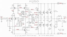
I've got a big problem! I've just made the Marcus' amp (M250) based on the schematics fuond at www.astro.uu.se/~marcus/private/m250.html
I've also made the dc-prot published on this forum. I've been redrawn PCBs (basing my project on Marcus' layout) using Fidocad (a small but
complete software!).
A note about components...
I haven't found the following items:
R5 715 Ohm replaced with (1k + 1,5k)//1k=714 Ohm
R22-30 0.33 Ohm " " 0.39 Ohm
PSU Caps 2x22000uF " " 5x4700uF
D5-6 1N4937 " " U1N4007 (Faster than classic 1N4007, is it true?)
D5-6 UF5406 " " UF5408
L1 Dia 20mm " " Dia 10mm (Not enought copper wire!)
The other components are the same as the ones in the original schematic.
Turning the amp on (both with and without the input signal) I measure about +50V (gnd ref).
All transistors stay cold also after 20 minutes in which the amp is on.
The LED is ON
Luckly, the DC-prot work fine because the relay stay open.
The drawing shows the voltages measured on my prototype (gnd ref).
I've just made one most test: I've replaced T4 and T5 because I thought they were burned.
After the substitution, turning the amp on, at the first time the output voltage increased from 0V to 50V in about 30 seconds.
Switching it on the second time, the same happened in just 1 second.
Unluckly I haven't any instruments to verify and test the amp accurately. I've got just a simple multimeter...
Do you have any idea about the problem occured in my amp and the solution?
Thank you in advance!
")
AngusMG
Hi everybody!
I've got a big problem! I've just made the Marcus' amp (M250) based on the schematics fuond at www.astro.uu.se/~marcus/private/m250.html
I've also made the dc-prot published on this forum. I've been redrawn PCBs (basing my project on Marcus' layout) using Fidocad (a small but
complete software!).
A note about components...
I haven't found the following items:
R5 715 Ohm replaced with (1k + 1,5k)//1k=714 Ohm
R22-30 0.33 Ohm " " 0.39 Ohm
PSU Caps 2x22000uF " " 5x4700uF
D5-6 1N4937 " " U1N4007 (Faster than classic 1N4007, is it true?)
D5-6 UF5406 " " UF5408
L1 Dia 20mm " " Dia 10mm (Not enought copper wire!)
The other components are the same as the ones in the original schematic.
Turning the amp on (both with and without the input signal) I measure about +50V (gnd ref).
All transistors stay cold also after 20 minutes in which the amp is on.
The LED is ON
Luckly, the DC-prot work fine because the relay stay open.
The drawing shows the voltages measured on my prototype (gnd ref).
I've just made one most test: I've replaced T4 and T5 because I thought they were burned.
After the substitution, turning the amp on, at the first time the output voltage increased from 0V to 50V in about 30 seconds.
Switching it on the second time, the same happened in just 1 second.
Unluckly I haven't any instruments to verify and test the amp accurately. I've got just a simple multimeter...
Do you have any idea about the problem occured in my amp and the solution?
Thank you in advance!
AngusMG
Attachments
Angus,
After staring at your schematic and looking at the PCB layout I'm seeing stars, flashing colors, and tiny purple elephants
Actually, no.
It seems like a problem with T8. Look at the voltage drop across R16. With 3.6V across 15 ohms you have 240mA flowing from the base of T8 to the collector of T18!!!
My first thought was that T8 might be shorted from collector to base but there is 0.9V across that junction. Check to see if you didn't accidentally put an MJE15031 in for T8. If a PNP were put in that posistion, the collector-base junction would be forward biased causing the base circuit to be pulled very close to the +V rail. T5 will probably be destroyed with that much voltage and current passing through it.
Also, make sure that you have the correct orientation of T3, T4, T5, and T18. The component layout drawing isn't very clear about which way to place them in the board. The pinout of MJE340 and MJE350 is ECB looking at the label side of the transistor. This is reversed from the MJE15030/31 pinout which is BCE. Looking at the voltages you have taken, you probaly have them correctly mounted. The problem is most likely T8.
Anyway, check T8. If it is the correct type (MJE15030) check the continuity. Maybe there is a partial short. You would be wise to replace T5 while you're at it since its life has probably been shortened severely.
Let us know what you find out.
transformer help
Hello, im interested in the m250, but i've a question, i wnat to do a stereo m250 so i'll have to do twice the schematic, one by chanel, but also i've to buy two transformers and capacitors por the power suply unit? or the 2x38, 500va is able to run the two chanels?
Hello, im interested in the m250, but i've a question, i wnat to do a stereo m250 so i'll have to do twice the schematic, one by chanel, but also i've to buy two transformers and capacitors por the power suply unit? or the 2x38, 500va is able to run the two chanels?
First Proto M250
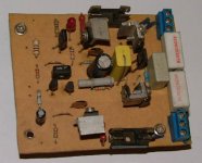
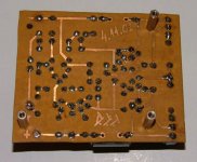
Just wana show da picture of first M250 proto that gave about 150 w rms 4 ohm 1% with a lower power supply. I didn't have a digital camera so...here it is....First PCB made in about 2 hours...didn't work at first...don't remeber why....but later i was very satisfied with this simple but functional schematic.
Many thanks to Marcus Gunnarsson for his help. Good Work !!!
Attachments
Commentable Thoughts
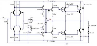
Ampman States That the M250 amplifier is unreliable amp due to folowing reasons:
1 The input differential is single ended.
2 Shared constant current source.
3 Complementary output stage.
4 Very low current gain of emitter follower stages.
Therfore due to above stated commentations M250 cannot be stated as reliable amp Acc to Professional Standards.
Regards
Ampman
Attachments
- Status
- This old topic is closed. If you want to reopen this topic, contact a moderator using the "Report Post" button.
- Home
- Amplifiers
- Solid State
- Another amp