Wavebourn said:Over years of experimenting with economical tube power amps I come finally to the solution used, as I found, long time ago by Altec Lansing in their 1569A amp. The wheel is reinvented... You are welcome to reinvent it again!")
I am happy that my amp looks like a classic good scheme. Any Ideas of how can I make it perform even better? Modifications suggested?
salas said:
I am happy that my amp looks like a classic good scheme. Any Ideas of how can I make it perform even better? Modifications suggested?
Yes. A phase splitter with separate anode and cathode loads between input amp and a differential cascade for better symmetry, all directly coupled. If you go with push-pull for power economy, go to the logical end instead of stopping on half-measures. It is my suggestion. However, the result will be again classical, but you come to it going by your own way.
salas said:Thanks. Do you have a link to such a classic schematic so I can study it?
Try: http://www.google.com
Good luck!

Edit: I've found it for you: http://www.one-electron.com/FC_ProAudio.html
Wavebourn said:
Do not advertise your secret membership of this community too much; other mortals might want to find things themselves otherwise
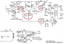
Well, here's the latest schematic. Mostly plagiarized from the Williamson, but I didn't like the biasing scheme for the outputs so I substituted my own. I figure tubes should draw around 45-50mA each. My only concern was leaving out the pot between the two 220K resistors after the .47uF coupling caps - is one needed?
EDIT: Once again, the OPT is the 6600-8 a-a 60W Edcor.
An externally hosted image should be here but it was not working when we last tested it.
EDIT: Once again, the OPT is the 6600-8 a-a 60W Edcor.
A phase splitter with separate anode and cathode loads between input amp and a differential cascade for better symmetry, all directly coupled.
Wavebourn, do you mean a Williamson type design?
EC8010 said:Swap the order of the 470nF and 47nF coupling capacitors.
I'm pretty sure it's been explained to me before, but why should I do that again? I'm hardly opposed to the idea but maybe I can learn something
ray_moth said:
Wavebourn, do you mean a Williamson type design?
I am weak in the History, donno who invented the wheel the first, before me...
I mean this one: http://www.triodeel.com/al1568a.gif
salas said:Along the same lines another classic.
I would go with direct coupling for better stability on low end. It may oscillate on infrasound. I did something similar back in 1974 being a teenager, Ind could not understand why it motorboats when I add a feedback more than certain level...
Direct coupling brings up another problem: with SS rectifier when it starts it whistles like a bird once.
salas said:I am happy that my amp looks like a classic good scheme. Any Ideas of how can I make it perform even better? Modifications suggested?
1) Get rid of this RC coupling. With a Vpp rail of 400Vdc at this point, direct coupling is certainly a viable possibility. RC coupling makes phase shift networks that can promote instability.
2) A solid state CCS will greatly improve the CMRR, and along with it, the AC balance of the LTP. Cascoded BJTs work quite well as tail CCSs. If you added the CCS and the DC coupling, you wouldn't even need an extra negative DC rail for it. By using such a CCS, you wonn't need unequal plate load resistors to cover up for the degraded CMRR that you get with a tail resistor. Also, I would try to use a VT with higher gain for this stage. 12AY7s would work well for this, in that its u is higher than that of a 12AU7 if you wanted to retain the nine pin mini. Otherwise, a 6SL7 would also work great for this. a higher gain device will also serve to improve the performance of the LTP splitter.
3) RC coupling with fixed bias is really bad. Let the signal go positive enough to turn on the gk parasitic diode, and the resulting clip behaviour will be wicked. Once that parasitic diode switches on, the bias increases negatively (how Class C amps get most, if not all, their operating bias) and forces the 6L6s into a less linear operating point. Since the gNFB loses effectiveness, the rising gain will deepen the clip. Given that the excess bias can only leak off through the 200K grid ressitors, it may never recover from a clip unless you turn the gain way down. I would definitely get rid of that by installing either a cathode follower driver (a good place for those 12AU7s -- even better: 6CG7) or, if you don't want to make another hole, a power MOSFET Common Drain driver. Either can easily be direct coupled to the 6L6 grids to prevent this particular problem. This type of driver also helps improve the slew rate for improved performance at the high end. Either that, or consider cathode bias for the finals.
Direct coupling brings up another problem: with SS rectifier when it starts it whistles like a bird once.
You can prevent that by sepearting the heater supply from the HV. Let the heaters warm up first before turning on the HV. That way, every stage is good to go, and all voltages will be correct, when you power up.
Attachments
Miles Prower said:
You can prevent that by sepearting the heater supply from the HV. Let the heaters warm up first before turning on the HV. That way, every stage is good to go, and all voltages will be correct, when you power up.
It is exactly what I mean.
I got rid of the problem adding couple of transistors (one for CCS, another for the tube current sensing - base in series with a tail resistor - that feeds CCS by current to ground).
Anyway, for biasing my 6L6 tubes at -35V, is it possible to have a separate negative bias supply (a small transformer regulated to put out 100mA of 135V)? I'd probably use a LM317 or something to bring down a 30VAC or so little transformer. Am I right in thinking that this increases the power output because there are no cathode bias resistors that burn off power?
sorenj07 said:Anyway, for biasing my 6L6 tubes at -35V, is it possible to have a separate negative bias supply (a small transformer regulated to put out 100mA of 135V)? I'd probably use a LM317 or something to bring down a 30VAC or so little transformer. Am I right in thinking that this increases the power output because there are no cathode bias resistors that burn off power?
There are all sorts of possibilities for this. You can connect the secondary of a cheap, 12Vrms "doorbell" xfmr to the 5Vrms rectifier filament secondary of the power xfmr if it's not being otherwise used. That'll give about 50Vrms. A fullwave bridge will give about 70Vdc. You may also get another heater xfmr and connect its secondary to the secondary of the existing heater xfmr to make the bias supply. Or you can get 1 : 1 isolation xfmrs and use that for the same purpose. Another possibility is a high frequency DC-to-DC inverter.
"Am I right in thinking that this increases the power output because there are no cathode bias resistors that burn off power?"
There will always be some power loss across the cathode bias resistors, however, the major culprit in that regard is the reduction of Vpk as a result of raising the cathodes above DC ground. What counts is the voltage between the cathode and the active elements. Raising the cathode by 35Vdc, reduces the voltage across the screen and plate by 35Vdc. That, in turn, will cause a power loss unless the DC rail voltage is increased by 35Vdc to compensate.
sorenj07 said:I'm pretty sure it's been explained to me before, but why should I do that again? I'm hardly opposed to the idea but maybe I can learn something
It reduces the duration of blocking distortion following a momentary overload - something that Miles mentioned in his section (3). As he said, even better is to drive the output stage from cathode or source followers.
- Status
- This old topic is closed. If you want to reopen this topic, contact a moderator using the "Report Post" button.
- Home
- Amplifiers
- Tubes / Valves
- Another 6L6 schematic