Giralfino: Nice work. I have more experience as a hobby furniture maker than a speaker designer, so I will comment from that perspective. Since you are done with the cabinet, my comments are more for discussion.
>Your laminated solid wood baffle will still move with changes in Relative Humidity but is unlikely to warp, so you will still have stress on the side to front joint.
>Your laminated MDF side panels look good but I would have built them on a form where you could provide more uniform clamp or vacuum pressure. If you routed template forms the same dimension as the cabinet ends, it should fit when transferred to the cabinet. The industrial method is shown on the Sonus Faber website but no DIYer would do it like that, although it gives you clues. My question is whether you would repeat your method if you make another pair?
>I made my own cherry veneer from stock to cover my MDF speaker cabinet including the front baffle. This technique assumes you have a bandsaw and a planar. You can look at FineWoodworking - Expert advice on woodworking and furniture making, with thousands of how-to videos, step-by-step articles, project plans, photo galleries, tool reviews, Blogss, and more for details on how to make and apply veneer
>The real proof is in how it sounds and the driver FR’s look good. Looking forward to your report on how they sound.
I'm not sure I'm understanding correctly, but my baffle is not laminated, it is what I think is called butcher block, made of roughly 2x20 cm strips. The end are joined with dovetail. In order to prevent any movement, the whole baffle is not glued to the rest of the speaker, it is bolted and the nut is like the one that can be seen in the last photo of the post #8. Between the baffle and the cabinet I glued a strip of sealing tape to the baffle.Your laminated solid wood baffle will still move with changes in Relative Humidity but is unlikely to warp, so you will still have stress on the side to front joint.
I found a photo here: Sonus Faber high end speakers follow the Italian lutherie tradition.Your laminated MDF side panels look good but I would have built them on a form where you could provide more uniform clamp or vacuum pressure. If you routed template forms the same dimension as the cabinet ends, it should fit when transferred to the cabinet. The industrial method is shown on the Sonus Faber website but no DIYer would do it like that, although it gives you clues. My question is whether you would repeat your method if you make another pair?
The problem I see is that if I have to build many curved parts (more than in the photo, because at 16 mm of thickness each I'd have needed more than 20 for a single speaker side), then it would have been better to build a translam type cabinet. That's a lot of work without a CNC machine, a lot of material, and a lot of money. All in all I'd build it again with my method.
As I said, the real problem was the first foil only, as it has a small surface to adhere to, but still a good surface once glued. I had to use some small nails in order to prevent any movement until the PVA glue could take effect. Subsequent foils were easy.
A thing I'd change are the aluminium L shaped bars (first photo in post #3), I'd use some bigger and stronger ones, and one or two more, and use 4 of the stronger orange straps. The bars are the "secret" for an even pressure.
No bandsaw here unfortunately, nor the space to accomodate one.I made my own cherry veneer from stock to cover my MDF speaker cabinet including the front baffle. This technique assumes you have a bandsaw and a planar.
Ralf
Very professionally made. I envy your fine detail / skils!. I also made a similar block for flush trimming using a router as you did. It comes in very handy when trimming two pieces together at odd angles, where guessing with a circular saw is very hit and miss.
Looking forward to your crossover schematics and posts. If using SpeakerWorkshop, and ARTA for measurements... does ARTA measure actual phase? or generate from the FR using an HBT (extract minimum phase)? If the latter - remember to include driver offset in the crossover in speakerworkshop. If actual measured phase is used - all speakers are at zero offset. I find using both is a good way to cross check measurements and crossover modeling.
Looking forward to your crossover schematics and posts. If using SpeakerWorkshop, and ARTA for measurements... does ARTA measure actual phase? or generate from the FR using an HBT (extract minimum phase)? If the latter - remember to include driver offset in the crossover in speakerworkshop. If actual measured phase is used - all speakers are at zero offset. I find using both is a good way to cross check measurements and crossover modeling.
Your woodworking skills are very impressive and the finished look is fabulous. I especially like the way you profiled the rear of the baffle to give maximum breathing for the woofer.
I wouldn't worry about the 2KHz bump my guess would be that this is a slight diffraction from the woofer surround as 2KHz is a wavelength of around 170mm and this is about the size of your woofer.
I wouldn't worry about the 2KHz bump my guess would be that this is a slight diffraction from the woofer surround as 2KHz is a wavelength of around 170mm and this is about the size of your woofer.
Thanks all for the kind words, but trust me when looking carefully there are a lot of imperfections. They simply doesn't show up in a small photo ")
But I'm satisfied in what I could do without a dedicated room, and with a rather limited equipment.
I had time today to perform some measurement, showing them in the next post.
Ralf
But I'm satisfied in what I could do without a dedicated room, and with a rather limited equipment.
I had time today to perform some measurement, showing them in the next post.
Ralf
Crossover and final measurements
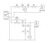
After a lot of simulations, measurements and listening time this is the crossover I’m using:
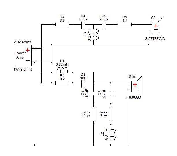
It is basically a LR4 design with asymmetrical slopes in order to compensate for the different acoustic centers. Electrically this is accomplished with a 2nd order network on the woofer and a 3rd one on the tweeter. On the woofer side there is also a notch for the breakup that helps also to reach the target slope (C1+R1), and a notch to flatten the midrange bump between 500 and 1000 Hz (L2+R3+C3, DCR of L2 is 1R7, if different change accordingly R3). On the tweeter side the two resistors R4 and R5 provide the attenuation needed.
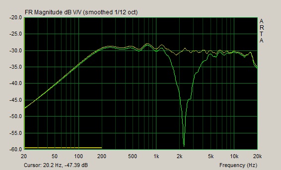
In the end I went for a crossover point at around 2400 Hz, a bit higher than I wanted, but couldn’t lower it without having a worse FR. I finalized the crossover with Speaker Workshop, but I now switched to XSim as it is much faster. I used the measurement done with Arta, calculated minimum phase and inserted the appropriate delay between the drivers. I found a measurement of the speaker I did when I finalized the crossover, showing the on-axis FR (drivers alone, combined response and reverse null):
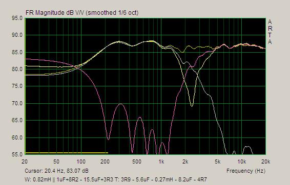
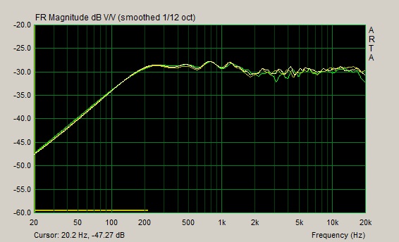
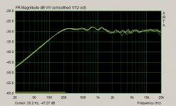
Today I performed some additional off-axis measurements, something that I only partly did in the past, just to understand if I were on the right track. First there is an image of the vertical off-axis FR, mic pointed at horizontal middle of the speaker, 0, 5 and 10 degree under the tweeter height. Green is 10 degree, the other 2 measurement are too close each other. At home the tweeter height is not below the listening height.
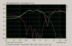
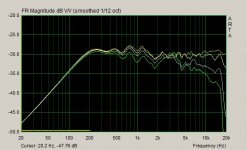
Next there is an image showing the horizontal off-axis FR, 0, 15, 30 and 45 degree (note, different scale as the previous image). It was the first time I did the 45 degree measurement, and this clearly shows that a lower crossover point could have probably helped in obtaining a better power response.
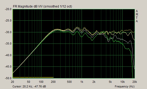
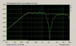
I’m showing also the 15 degree horizontal off-axis FR alone, with its reverse null. This shows that the sweet spot is fairly large horizontally, and the speakers can be positioned flat or only slightly toed-in.
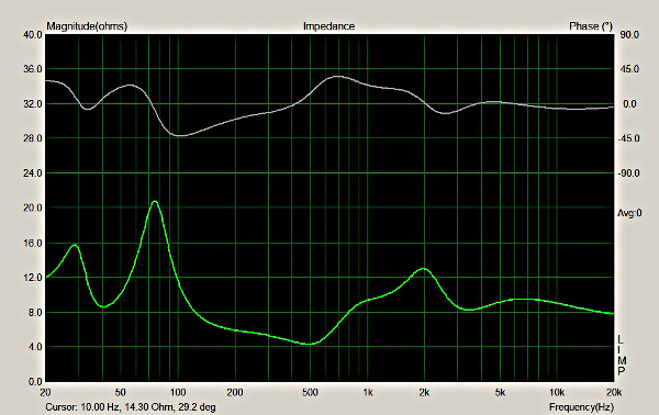
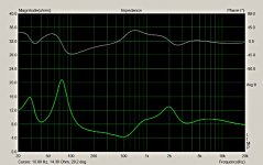
Last the measured impedance, a relatively easy load. The tuning shown here is a bit lower than what I’m using now, 40 vs 42Hz.
Ralf
After a lot of simulations, measurements and listening time this is the crossover I’m using:
It is basically a LR4 design with asymmetrical slopes in order to compensate for the different acoustic centers. Electrically this is accomplished with a 2nd order network on the woofer and a 3rd one on the tweeter. On the woofer side there is also a notch for the breakup that helps also to reach the target slope (C1+R1), and a notch to flatten the midrange bump between 500 and 1000 Hz (L2+R3+C3, DCR of L2 is 1R7, if different change accordingly R3). On the tweeter side the two resistors R4 and R5 provide the attenuation needed.
In the end I went for a crossover point at around 2400 Hz, a bit higher than I wanted, but couldn’t lower it without having a worse FR. I finalized the crossover with Speaker Workshop, but I now switched to XSim as it is much faster. I used the measurement done with Arta, calculated minimum phase and inserted the appropriate delay between the drivers. I found a measurement of the speaker I did when I finalized the crossover, showing the on-axis FR (drivers alone, combined response and reverse null):
Today I performed some additional off-axis measurements, something that I only partly did in the past, just to understand if I were on the right track. First there is an image of the vertical off-axis FR, mic pointed at horizontal middle of the speaker, 0, 5 and 10 degree under the tweeter height. Green is 10 degree, the other 2 measurement are too close each other. At home the tweeter height is not below the listening height.
Next there is an image showing the horizontal off-axis FR, 0, 15, 30 and 45 degree (note, different scale as the previous image). It was the first time I did the 45 degree measurement, and this clearly shows that a lower crossover point could have probably helped in obtaining a better power response.
I’m showing also the 15 degree horizontal off-axis FR alone, with its reverse null. This shows that the sweet spot is fairly large horizontally, and the speakers can be positioned flat or only slightly toed-in.
Last the measured impedance, a relatively easy load. The tuning shown here is a bit lower than what I’m using now, 40 vs 42Hz.
Ralf
Attachments
Some random things
On a lazy Sunday afternoon I thought I have something more to share.
This post is mainly to share something I found when switching from the test crossover to the final one (or, what I thought was the final one at that time).
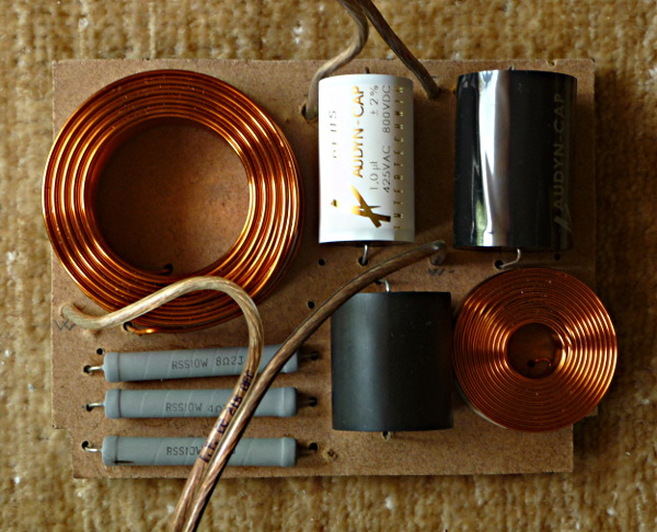
I built and tweaked the test crossover using cheap components. This should not be a problem with resistors and coils, but with caps cheap means electrolytic, but an electrolytic cap has definitely a higher ESR in respect to a film one (at least for small capacitance values, until some uF). So when I built the then final crossover simply changing component types (MOX for ceramic resistors, film for electrolytic caps, air core for cored coils), my crossover was slightly off, so I had to re-tune it. Moral of the story: if you want to test a crossover with cheap components before buying the final ones buy a set of cheap film caps instead of electrolytics up to 10uF. Over 10uF the difference in ESR between the two cap types should be negligible.
This is how I built the crossover. The components are glued to a 5/6mm thick MDF panel, and are soldered on the rear. The panel has small 1.5cm square feet made again with 5/6mm MDF that provide the needed clearance for the wires under the panel. The crossover board is secured into place using small pieces of blue tack under the feet so it can be easily removed and restored. A photo of the woofer board:
Someone asked about the bass. These speakers are obviously not bass shakers, and I chose to tune them lower than what all calculators suggest, at around 42-44 Hz, because so they interact better with the room gain providing a useful response down to 40 Hz, with a shallow slope avoiding the single-note-bass effect.
Currently I’m working on a 3-way speaker for my sister. My crossover skills are better now than when I finalized this 2-way, and I’m sure I can manage to lower the crossover point. So when I’m done with the current project I probably will revisit the speakers.
Ralf
On a lazy Sunday afternoon I thought I have something more to share.
This post is mainly to share something I found when switching from the test crossover to the final one (or, what I thought was the final one at that time).
I built and tweaked the test crossover using cheap components. This should not be a problem with resistors and coils, but with caps cheap means electrolytic, but an electrolytic cap has definitely a higher ESR in respect to a film one (at least for small capacitance values, until some uF). So when I built the then final crossover simply changing component types (MOX for ceramic resistors, film for electrolytic caps, air core for cored coils), my crossover was slightly off, so I had to re-tune it. Moral of the story: if you want to test a crossover with cheap components before buying the final ones buy a set of cheap film caps instead of electrolytics up to 10uF. Over 10uF the difference in ESR between the two cap types should be negligible.
This is how I built the crossover. The components are glued to a 5/6mm thick MDF panel, and are soldered on the rear. The panel has small 1.5cm square feet made again with 5/6mm MDF that provide the needed clearance for the wires under the panel. The crossover board is secured into place using small pieces of blue tack under the feet so it can be easily removed and restored. A photo of the woofer board:
Someone asked about the bass. These speakers are obviously not bass shakers, and I chose to tune them lower than what all calculators suggest, at around 42-44 Hz, because so they interact better with the room gain providing a useful response down to 40 Hz, with a shallow slope avoiding the single-note-bass effect.
Currently I’m working on a 3-way speaker for my sister. My crossover skills are better now than when I finalized this 2-way, and I’m sure I can manage to lower the crossover point. So when I’m done with the current project I probably will revisit the speakers.
Ralf
Attachments

- Status
- This old topic is closed. If you want to reopen this topic, contact a moderator using the "Report Post" button.
- Home
- Loudspeakers
- Multi-Way
- Another 6.5”+1” BR design (Peerless HDS + Seas Prestige)