OK, glad I asked. There's a bunch of problems there, especially in the first three stages (think about what the grid and cathode voltages need to be) and we have to think about how to bias up the heaters (NOT grounded on one end!) to avoid challenging the maximum cathode-heater voltage spec.
Indeed. Where did this come from?
Sheldon
Didn't have time for a detailed response yesterday, hence the cryptic response. The real question is: Do you have a circuit that you are trying to emulate? What are your design objectives - gain, noise, and so forth?
As SY intimated, the circuit as shown has some problems. For instance, you have the cathodes of the first two stages tied together. With any reasonable operating point for either section, that means that the grids will be within a few volts of one another. But you have the grid of the second section tied to the plate of the first section. This will certainly be more than a few volts higher than the grid for the first section. The third section has similar considerations. The overall gain with three AX7 sections will be very high. Do you need all this gain? This needs some rethinking.
Sheldon
Last edited:
I am sorry I posted that previous schematic as it was.
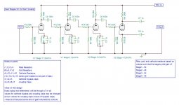
Over the last three days I spent some time examining the gain stage of the 12ax7. I started a fresh page and created this new schematic (see attached)
The resistor and cap ratings are not listed, and there are a some questions about some of the values. I got the resistor values using the datasheet chart for the desired gains. I am going to alter the PSU for a 180vdc b+ for this to work.
This is only the schematic for the gain stages and not for the heaters.
now assuming I am on the right track...
here are my questions for the community:
-- Should i be using polarized caps for the coupling and bypass caps?
-- I am unsure how to determine the values for the series grid resistors after the first stage (went with a standard 68k for the first, but the 50k values for the other 3 have no reasoning)
--Should the output (from the last stage) come off the plate or the cathode? ( i have read that you can use the cathode as output if it does not have a bypass cap)
--how would i calculate the total gain for all stages?
I was using the chart on this datasheet to find the resistor values to control the bias voltage and gain for each stage
12AX7 pdf, 12AX7 description, 12AX7 datasheets, 12AX7 view ::: ALLDATASHEET :::
(chart is on the top of the 2nd page)
I didnt understand the need for the Rs resistor in this diagram. My schematic would call for all the Rs to be 240k. Is this a nessasary component?
Attachments
Thanks SY for the quick response- I need to address these issues so Im glad you asked-
I was unsure about the series grid resistors. I thought they would keep the gain down and stabilized the tone. They may not be nessasary
the last stage was intenionally left unfinished- The ground you see going to the output is not the signal output, just where the output is grounded. I didnt know if i should output signal through the cathode or plate of the last stage
as for the b+ and gains, i pulled them from the datasheet. I dont have a good sence of associating gains with their actual sound, so I didnt realize i chose such high gains. What would be a suitable total gain from a preamp?
I have only looked at this one datasheet and it has led me to belive that the 12ax7 will run off 180vdc (with300v max)
Here is the bit i read that influanced me to add those resistors (when you said "stoppers" manshaffer it reminded me where i read this) also, this is a guitar preamp-
"""
The Grid Resistor, also called the Grid Stopper Resistor
The grid resistor can also control gain between stages and also interacts with the tube to roll off highs. Values can be from 1.5K to 100K. Larger values roll off more highs and reduce gain between stages. The grid stopper resistor works best when mounted directly, or as close as possible, to the grid pin. In almost all tube amps you will find a 68K resistor on the very first grid pin. This resistor can help block radio frequency interference.
"""
pulled from Vacuum tube gain stage
"""
The Grid Resistor, also called the Grid Stopper Resistor
The grid resistor can also control gain between stages and also interacts with the tube to roll off highs. Values can be from 1.5K to 100K. Larger values roll off more highs and reduce gain between stages. The grid stopper resistor works best when mounted directly, or as close as possible, to the grid pin. In almost all tube amps you will find a 68K resistor on the very first grid pin. This resistor can help block radio frequency interference.
"""
pulled from Vacuum tube gain stage
Last edited:
I was unsure about the series grid resistors. I thought they would keep the gain down and stabilized the tone. They may not be nessasary
the last stage was intenionally left unfinished- The ground you see going to the output is not the signal output, just where the output is grounded. I didnt know if i should output signal through the cathode or plate of the last stage
as for the b+ and gains, i pulled them from the datasheet. I dont have a good sence of associating gains with their actual sound, so I didnt realize i chose such high gains. What would be a suitable total gain from a preamp?
I have only looked at this one datasheet and it has led me to belive that the 12ax7 will run off 180vdc (with300v max)
You need to tell us what you want from this amp? How much gain do you need? This can be calculated from the input level to the preamp and the required input level for your next stage. What frequency response do you want?
You seem to want to go through the design process, rather than follow an existing design. Fine, you will get help here. But you need to tell us what you want. The design process starts from the required output and works backward to the input.
You seem to want to design an amp, not copy a finished design. That's fine, you will get help. But you need to tell us what you want from the amp. The design process starts from the output required, and works backwards to the input.
Those grid resistors will reduce the gain, but also your high frequency response. Even with those in place the first three stages have a gain of almost 2000.
Gain is not directly associated with sound. It's what you need to get a low level signal to the next stage.
The 12AX7 will run at 180V on the plate. But don't confuse that with B+. B+ is the power supply voltage to the plate resistor, not the plate.
The configuration of the last stage depends on what you are feeding.
Sheldon
posted while you did. Note that roll off of the high value grid stoppers will add in series. With four is series, you have a forth order filter, with a steep roll off.
Last edited:
A stopper must be put right on the socket pin and with as short of lead as possible. Its purpose is to prevent tube from becoming an oscillator. It needs to be on the other side of the grid leak resistors (downstream). For example R12 needs to be to the right of R5.
The grid leak resistor which is the resistor to ground from the grid (R5,6,7,8) in combination with their respective coupling caps will comprise a frequency dependent voltage divider which can be used to limit low frequency response.
If that right most tube is supposed to be a phase inverter (cathodyne) for driving a push pull output then it is going to be grossly out of balance with those two highly unequal load resistors. If they are separate (low Z high Z) outputs they may be OK.
Some data sheets for 12AX7 with give gain charts for various configurations. Off the top of my head I would guess that with decent B+ (i.e. closer to 300V) you should get at least 40 or 50 per stage at the plate so what... about 100dB after the third stage. I would say that three 12AX7 gain stages should give plenty of overdrive for a guitar preamp.
Remember to account for voltage swing at the grids. In general you can't swing more than the bias voltage without clipping.
- Status
- This old topic is closed. If you want to reopen this topic, contact a moderator using the "Report Post" button.
- Home
- Amplifiers
- Tubes / Valves
- another 12ax7 preamp