What are the voltages this amplifier can drive into 8r0 and 4r0 test loads without clipping of the signal?
I had a PC based signal generator, now as the amp has proper heatsinks and power supply, i took a quick test without frying the drivers.(I don't have a dummy load and oscilloscope)
I played 37, 45, 50, 1000 Hz tones until I could hear possible distortion and got the voltages at the output driving a speaker with 4 ohms impedance and 3.5 ohm DC resistance as below:
37 Hz: 31.1V AC rms
45 Hz: 31.4V AC rms
50 Hz: 31.8V AC rms
1000 Hz: 32.6V AC rms
Also, the supply rails were +/-49.4V DC unloaded.
Regards,
Aniket
Roughly 30V rms @ 4ohm load gives us 225W output power... must be not easy to listen to, huh? ))
Yeah, my households were rattling like hell, that too with both channels driven

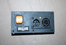
I actually use even the "bigger" one - with the main power switch
I have one where the switch have gone faulty
and I cannot find an exact replacement that fits
I prefer them seperate from now on
fuse drawer is still handy though
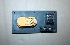
might be practical to have it all on seperate small alu plate, and then mount as a unit
out of necessity I did this not long ago
Attachments
Nice Aniket !
Aniket I did check the design and it does respond really well here are some
results:
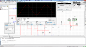
20Hz 1Vp signal at 8 ohms load give about 48W and 0.001% THD
20Hz 1.5Vp signal at 3.8 ohms load give about 231W and 0.002% THD
20KHz 1.5Vp signal at 3.8 ohms load give about 158W and 0.151% THD
I did exaggerate a bit the speaker load "3.8 ohms" because is not always exactly 8 or 4 ohms, and I usually check only with 20Hz and 20KHz, go beyond 20KHz will serve not purpose lol in my opinion
20Hz looks pretty clean and 20KHz
Regards
Juan
Aniket I did check the design and it does respond really well here are some
results:
20Hz 1Vp signal at 8 ohms load give about 48W and 0.001% THD
20Hz 1.5Vp signal at 3.8 ohms load give about 231W and 0.002% THD
20KHz 1.5Vp signal at 3.8 ohms load give about 158W and 0.151% THD
I did exaggerate a bit the speaker load "3.8 ohms" because is not always exactly 8 or 4 ohms, and I usually check only with 20Hz and 20KHz, go beyond 20KHz will serve not purpose lol in my opinion
20Hz looks pretty clean and 20KHz
Regards
Juan
Attachments

20KHz 1.5Vp signal at 3.8 ohms load give about 158W and 0.151% THD
20kHz THD looks a bit high for such schematic, meaning the open-loop bandwidth is not high enough, which is sometimes a result of over-compensation.
Try to reduce C3 in simulation and you'll see the improvement. Now, the trick is to find the optimal value for enough stability and rather low distortion at higher end...
It seems like for those bias currents that C3 and C18 at 100pf are a bit large. Perhaps it is being overcompensated? Perhaps reducing the lag compensation and adding phase leading compensation? such as a small pf cap in series with a resistor (a zero) placed in parallel with R29.
20kHz THD looks a bit high for such schematic, meaning the open-loop bandwidth is not high enough, which is sometimes a result of over-compensation.
Try to reduce C3 in simulation and you'll see the improvement. Now, the trick is to find the optimal value for enough stability and rather low distortion at higher end...
I will try out that sir reducing C3 and C18
Last edited:
Aniket I did check the design and it does respond really well here are some
results:
20Hz 1Vp signal at 8 ohms load give about 48W and 0.001% THD
20Hz 1.5Vp signal at 3.8 ohms load give about 231W and 0.002% THD
20KHz 1.5Vp signal at 3.8 ohms load give about 158W and 0.151% THD
I did exaggerate a bit the speaker load "3.8 ohms" because is not always exactly 8 or 4 ohms, and I usually check only with 20Hz and 20KHz, go beyond 20KHz will serve not purpose lol in my opinion
20Hz looks pretty clean and 20KHz
Regards
Juan
Thanks Juan,
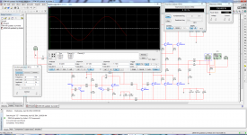
Multisim is a very conservative simulation software and it's simulation results are very much close to the actual real world performance.
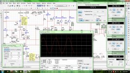
On the other hand I am getting a lot better THD performance in simulation.
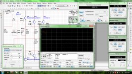
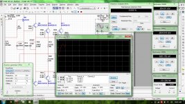
1kHz 1.7Vp input signal on 8 ohms load gives 131W output, 0.001% THD
20kHz 1.7Vp input signal on 8 ohms load gives 131W output, 0.005% THD
1kHz 1.6Vp input signal on 4 ohms load gives 233W output, 0.001% THD
20kHz 1.6Vp input signal on 4 ohms load gives 232W output, 0.014% THD
pics attached
20kHz THD looks a bit high for such schematic, meaning the open-loop bandwidth is not high enough, which is sometimes a result of over-compensation.
Try to reduce C3 in simulation and you'll see the improvement. Now, the trick is to find the optimal value for enough stability and rather low distortion at higher end...
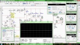
I already checked various values of C3 in simulation. For 47pF THD20 falls to 0.007% for 4 ohm load at 232W output.
In fact I reduced the value of C3 in the working model and the amp was stable upto 47pF( i checked 100, 82, 56, 47, 39pF ), below than this it was oscillating.
So I left 100pF as a fail safe value in the place of C3.
It seems like for those bias currents that C3 and C18 at 100pf are a bit large. Perhaps it is being overcompensated? Perhaps reducing the lag compensation and adding phase leading compensation? such as a small pf cap in series with a resistor (a zero) placed in parallel with R29.
Yep, I agree it's a little(not much) over compensated. The optimal value for C3 would be 68pF, maintaining stability and gaining some high frequency performance as well. I didn't had it in stock. would buy 68pF 1kV ceramics on my next parts purchase.
Regards,
Aniket
Attachments
On the other hand I am getting a lot better THD performance in simulation.
1kHz 1.7Vp input signal on 8 ohms load gives 131W output, 0.001% THD
20kHz 1.7Vp input signal on 8 ohms load gives 131W output, 0.005% THD
1kHz 1.6Vp input signal on 4 ohms load gives 233W output, 0.001% THD
20kHz 1.6Vp input signal on 4 ohms load gives 232W output, 0.014% THD
OK, these are the values I would expect from the schematic
I'm not an expert but I think this design will perform really really well, remember we are testing in a virtual simulator and we are pushing to the limits and still making good lower THD with 20KHz so I imagine that is a really quiet amp, and I betcha in the real world will outperform even better that is for sure.
Regards
Juan
Regards
Juan
I'm not an expert but I think this design will perform really really well, remember we are testing in a virtual simulator and we are pushing to the limits and still making good lower THD with 20KHz so I imagine that is a really quiet amp, and I betcha in the real world will outperform even better that is for sure.
Regards
Juan
DIY 120W amplifier sound test - YouTube
Have a look on the video on the above link, it sounds brilliant, very open and detailed
Aniket those Pionner woofers are 4 ohms ?
Yep, those are TSW-1208D2 400W, each with dual 2 ohm voice coil, connected in series to make a 4 ohm load.
oh that explains I think they are way too stiff "rigid" for your amp if you get paper cones woofers at 8 ohms even 10" woofers size man that would sound magnificent
I have two Alpines type R woofers and they barely move jejejejejeje love your video bro it does motivate me
Regards
Juan
I have two Alpines type R woofers and they barely move jejejejejeje love your video bro it does motivate me
Regards
Juan
- Home
- Amplifiers
- Solid State
- Another 100W hifi amp