Here's a possible geometric solution for a PLT with a fixed length tonearm.
Stylus to arm end is fixed length but stylus to pivot is NOT fixed length obviously. It's still going through the "elongation" process. However, the way you've drawn up makes the guiding mechanism easier because the back end curve is much smoother so a track or rail will be easier to make. Or even a cam system. Good job!
[emoji4] I'll sign it for you [emoji14]2wice,
I'm going to print those images and frame them.
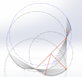
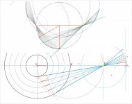
It seems they are all arcs.
Top curve arc is part of 300mm dia circle, perhaps slightly smaller.
Bottom right curve is part of circle that also passes through spindle and pivot.
Bottom left curve nearly goes through pivot.

The guiding mechanism could be a rod, its length equal to the radius of the top circle, that is attached between the centre of this circle and the rear of the arm. A possible drawback is that the pivot would have to be either beneath or above the platter.
Niffy
Hiten,
A unipivot with an additional CW might work, but since horizontal mass is a concern, I don't think I would do that. Mark Kelly did something similar with his two straw PLT, but I don't think it was a unipivot. A pre-loaded bearing works very well there and can be inexpensive.
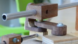
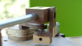
The photos are of a hybrid unipivot I've used. A pin and ruby cup would work for the top bearing and I think a ruby bushing might work at the bottom. For a Birch or Schroeder arm, the main arm has to be attached to the guide somehow.
A unipivot with an additional CW might work, but since horizontal mass is a concern, I don't think I would do that. Mark Kelly did something similar with his two straw PLT, but I don't think it was a unipivot. A pre-loaded bearing works very well there and can be inexpensive.
The photos are of a hybrid unipivot I've used. A pin and ruby cup would work for the top bearing and I think a ruby bushing might work at the bottom. For a Birch or Schroeder arm, the main arm has to be attached to the guide somehow.
Attachments
Thanks Doug. Pictures are making things clear. With limited knowledge and so many factors, geometry of movement, varioud pieces of wands and pivots it is little difficult for me to understand. If any kind soul does very basic animation we can feel the working of tonearm.
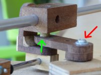
I am indeed talking about unipivot+sleeve type jewel bearing. Unipivot at green arrow and jewel bearing at red arrow. The unipivot would help in warped records.
If longitudinal groove force is pulling the tonearm and if we are going for very low friction wouldn't that affect sound reproduction. for example suppose a large amplitude low frequency modulation occurs it will move tonearm wand back and forth. So a calculated friction at main pivot (red arrow) will be good and extremely low unipivot at green arrow. Isn't it?
Regards.
Attachments
Pardon.If any kind soul does very basic animation we can feel the working of tonearm.
I think more or less I got it of how this works.
Regards.
Great job 2wice: your nice curves demostrate also that what I've surprisingly found as a line it's not a line but a curve. (math wins compass one - nil) Very helpful for my trial too. Waiting bearing's arrival i'm now making more precise measures and a new model.
Fortunately making a Thales of 300 mm (equal to the diameter of an LP to simplify the calculations) the curve considered (21 °) even if not a line is really near, and maybe brings to irrelevant tolerances for construction.
The good thing is also that thanks to your curves now the mistery to find less errors on the mock up than on paper becomes clear. The error derives from the difference between an arc and his chord, but getting an arc instead of a line acts in negative. A small advantage.
Carlo
All these geometries, when deeper investigated, maybe slowly lead to Thales: a new theorem, after 2500 years, seems improbable to find.
Attachments
The internal details of these excellent drawings may help explain the slight inherent tangent error in the Birch design and some very frustrating problems I had with my Birch builds.
Alas, poor compass. I just couldn't get a circle arc to precisely fit the point traces I made.
Alas, poor compass. I just couldn't get a circle arc to precisely fit the point traces I made.
Attachments
Only thing needed now is a frictionless sliding pivot.
First, 2wice's second drawing is a thing of beauty. I should print it and pin it to the wall like a poster!
I think reducing vertical arm's mass will help reducing friction so I'm sticking to the Dynavector style split-plane design. Might use a thin carbon fiber rod to extend from carriage to behind (or in front of) the pivot point and then deal with the guiding mechanism there, which can be another pivot to the radius of the top circle, as Niffy suggested, or a curved track/rail, or string+pulley, or cam, or a running squirrel, or whatever!
Hey, thanks to all the contributors I think this thread is going somewhere.
")
Houston, we have a problem .... Me too, 2wice.
I tried to apply your graph to my extensible Thales to control the measurements, and (damn) an error bigger than with my line appeared. Especially when the arm approaches the spindle.
Since the syrinx graph is drawn moving and rotating always the same segment (maybe the same condition imposed in your math) that was really strange.
So I went directly to your graph and put a segment equal to the others (250mm) on the spindle and turned it to pivot: out of the curve, 5 mm error again. Strangely the error appears only from the last groove to the spindle: practically irrilevant of course, but maybe not geometrically.
Where i'm wrong?
carlo
dimensions in red made automatically by the program, not written by me
Attachments
Hiten,
The axis for the vertical movement takes care of warps and cuing. The part that connects to the control rod also takes care of azimuth. Its bearing at the vertical movement axis could be a pin, cup, and ring magnet, but that's a bit complicated and expensive.
The axis for horizontal movement has to be completely vertical and stable just like a conventional pivot arm. There are both radial and axial forces there and the cantilever carrying the arm puts the bearing(s) under a lot of stress in this type of design.
Attachments

Last edited:
Hi Carlo
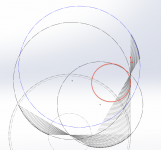
That is because only the bottom right curve falls on a circle and is a true arc by design.
The top and bottom left curves are derived and has a max deviance of 20um off the arc in that segment of that curve. It gets bigger the closer you get to the spindle.
Most manufacturing methods will be hard pressed to beter that error.
I would manufacture from the point data rather than from the arc that's just a best fit.
This is what the completed curve looks like, but you don't need that bottom lip.
Hi Carlo
That is because only the bottom right curve falls on a circle and is a true arc by design.
The top and bottom left curves are derived and has a max deviance of 20um off the arc in that segment of that curve. It gets bigger the closer you get to the spindle.
Most manufacturing methods will be hard pressed to beter that error.
I would manufacture from the point data rather than from the arc that's just a best fit.
This is what the completed curve looks like, but you don't need that bottom lip.
Fascinating!
The inner beauty of reality!
I was surprised from that unespected shift almost like discovering that hidden "line". Since is not completely a circle, now i feel freer to comtinue to use it without blame: easier to check and measure.
grazie - carlo
my son worked 3 years in joburg, where you live?
I was surprised from that unespected shift almost like discovering that hidden "line". Since is not completely a circle, now i feel freer to comtinue to use it without blame: easier to check and measure.
grazie - carlo
my son worked 3 years in joburg, where you live?
Last edited:
- Home
- Source & Line
- Analogue Source
- Angling for 90° - tangential pivot tonearms