thanks to Mark.
Mark,
thanks for the pointer (sorry for the pun, but it IS intended). I was looking for some kind of continuous data across the complete LP to create a smooth curve...although your statement suggesting the use of a simple pointer is a good one.
Esparado:
Although I consider myself an audiophile, I do have a healthy respect for the physical laws. Or perhaps I am more of an "equipment-phile"") . It does seem that many also forget that it is the experience of listening to music that is what the hobby is about. If we don't listen to the music we profess to enjoy, why bother with any of this! It then only becomes an academic exercise.
. It does seem that many also forget that it is the experience of listening to music that is what the hobby is about. If we don't listen to the music we profess to enjoy, why bother with any of this! It then only becomes an academic exercise.
Mark,
thanks for the pointer (sorry for the pun, but it IS intended). I was looking for some kind of continuous data across the complete LP to create a smooth curve...although your statement suggesting the use of a simple pointer is a good one.
Esparado:
Physical laws are resilient, even against troops of believers audiophiles witch ignore them.
Although I consider myself an audiophile, I do have a healthy respect for the physical laws. Or perhaps I am more of an "equipment-phile"
. It does seem that many also forget that it is the experience of listening to music that is what the hobby is about. If we don't listen to the music we profess to enjoy, why bother with any of this! It then only becomes an academic exercise.If we don't listen to the music we profess to enjoy, why bother with any of this! It then only becomes an academic exercise.
Academic exercise can be fun, too!
I enjoy both. But listening to music is very personal so I rarely talk about it on a forum like this.
Silence is also very precious . . . . . .
Mark,
thanks for the pointer (sorry for the pun, but it IS intended). I was looking for some kind of continuous data across the complete LP to create a smooth curve...although your statement suggesting the use of a simple pointer is a good one.
You can always make lots of pointer measurements and then join the dots.
I am the inventor of the arm in post #352, and I, too, have been curious about a translation of the Japanese magazine mentioned (available on Picasaweb in a Neil Baylis album.). I built a similar arm on the way to the patent but didn't pursue it because "it wasn't perfect." I recently revived it as a test object to see if it really needs anti-skate compensation. I am trying to assess if 2 degrees of tracking error (less when weighted) is fatal, in the face of possibly no anti-skating requirement (the same viewpoint that RS has). Also, it is possible that a good conical stylus would complement the arm better than a possibly-misaligned elliptical, or similar. Just because the builder draws it symmetrically doesn't mean we have to mount it that way.
What an honor that this thread is visited by an inventor! Thanks for contributing, Mr. Wolff. I, too, would like to see a translation of the Japanese text of the stringed tonearm. Can you tell us more about your design? Or any pictures you would like to share? I know you referenced patent# 2516565 from inventor Gleo C Guy in 1950 and his design is geometrically similar to the Thales. So your arm would attempt to keep tangency. Do you think the Japanese arm is trying to do the same thing?


Hi, DD
I should know better than to start an intro with a pompous-sounding "I am." The "honor" is mine; you guys are incredible. And thanks for referencing my patent!
Everyone strives for tangency since that seems to agree with the cutting procedure, but it has its limits in reality, and that's where engineering comes in. Pressing errors, off-center holes, poor styli, inaccurate cantilever position in the generator, et al. Not to mention rather high VTFs these days.
My arm was made to track perfectly, and it does. So do some others. But that's not the whole story. Can those arms trace a groove while tracking a warp, or is the moving mass too high? How about the horizontal axle height? Has it been compromised by a search for a better VTA? Has the effort to beautify the arm resulted in using metal where a lighter material would be better?
If I understand correctly, Frank Schroeder is striving for an arm that should be free from bias (skating) compensation. That's a very canny decision. That feature has kept the SLT faction in business for 50 years. Its a pain to adjust and varies with too many things to be completely accurate (of course, it may not need to be, since its basically a "compliance-restorer"). When I started, I noted that the bias error in my arm started at 17 degrees (versus a constant 23 degrees in a fixed-offset arm) and needed some compensation. When the arm got to the end of the record, the error was less than seven degrees and was a don't-care. At what point could I chuck the compensator? It is different in a V15III (60 compliance units) versus a Koetsu (9cu, and I own one only in my dreams!).
Jumping around in the interest of brevity. Yes, Glen Guy's patent was the source for much of my design, as it was for van Eps, Thales, etc. Articulating-head tonearms pre-date Percy Wilson's overhang-and-offset fix, you know (1924). I'm rereading Guy's and Yasuda's patent (2192464) to see who inspired the mystery-string design we're all impressed with. Your friend Yosh, and Marek Bundzel have some interesting viewpoints, too.
To answer your question about the arm in the Japanese magazine: The arm describes an arc, and having a pulley ratio of 1:1 means that the arm angle is the same as the head angle. At its center-of-the-record starting position, the cantilever is tangent to some groove. As the arm goes to either side, the cantilever is still parallel to its starting point, but no longer pointing to the spindle. This error can be halved by siting the arm a bit closer so that it overhangs the starting radius slightly. Now, it never is perfectly perpendicular to a radius, but the error is only a degree or two. That might be tolerable if no skating compensation is needed. I'm trying to determine that for myself. All the two-arm and string designs are trying to achieve an asymmetric version of this same design to track perfectly at least over the record surface, the heck with outside it. There is an awareness that perfect tracking over the label is useless, but we may be able to turn it to some advantage by re-siting the arm pivot.
Although I own a Harmon-Kardon ST-7 linear tracker (great for seeing how much better pivoting designs sound), I have always known how those puppies go out of tangency at the microscopic level because of the baggage they must carry, air-bearing or motor-assisted not withstanding.
I applaud your contributions to the articulated-head cause, and all the other contributors to this thread.
If I seem a little mum about my own design, you may infer that there is a reason. And I understand Ralf's situation all too well! If I make it out of the starting gate this time, it'll be a miracle!
Andy
Slight correction to my previous comment on the tonearm in the unknown Japanese magazine: I wrote:
"The arm describes an arc, and having a pulley ratio of 1:1 means that the arm angle is the same as the head angle." This should have been:
"The arm describes an arc, and having a pulley ratio of 1:1 means that the head angle is the same at any arm angle."
That's the reason the author's diagram shows the pickup at the same angle at all head positions, specifically the lead-in and lead-out grooves. A perpendicular line drawn from the stylus/cantilever doesn't pass through the spindle at all positions along the arm arc.
Many designers have tried to flatten that arc besides the obvious (and impractical one) of lengthening the arm. The usual fix is to add some sort of mechanism for sensing the arm position and make the pivot move to lengthen or shorten the distance to the stylus in a kind of inverse arc. Said extra mechanism usually equals excessive friction.
Sorry for the error!
Andy
<snip> At its center-of-the-record starting position, the cantilever is tangent to some groove. As the arm goes to either side, the cantilever is still parallel to its starting point, but no longer pointing to the spindle. This error can be halved by siting the arm a bit closer so that it overhangs the starting radius slightly. Now, it never is perfectly perpendicular to a radius, but the error is only a degree or two. <snip>
Andy
I think you are making this more confusing than it needs to be. The diagram from the patent shows that the arm is not tangent at its centre position and the calculation of the error has already been given. Moving the pivot backwards to lessen this error increases the errors at the ends of travel - no free lunch. I guess what you are saying is equivelent to this in reverse order. I wonder at the point of this all - it adds complexity and potnetial for extra friction whilst providing almost no improvement in tracking error.
With any design like this, the skate force is computable by considering the offset between the groove tangent at the stylus contact point and the arms pivot. If the two poulleys are of equal diameter, there is at most one point where this is zero.
Last edited:
Mark,
Thanks for your input. I was trying for clarity & may have missed.
The diagram I am working off is shown in reply #351 (not a patent). However, all your comments are correct.
"The point of it all" is that this is a good "thought experiment."
The re-siting of the arm pivot avoids tracking the label area and thus narrows the arc to be traversed by the arm to just the grooves. This in turn narrows the total head-to-arm angle which causes skating force.
The author positioned the arm at the center of the grooved area, cutting this skating angle in two. This gave one zero tracking error point (his "starting" position, the middle, as you noted). I suggested moving the arm pivot a tiny bit leftward (in the diag. in #351) which now produces two zero points, but the arm is still traversing an arc.
My final points were these:
(1) All of this is well-known. Various authors, inventors et al have come up with "the final fix" which is either a cam that moves the arm left and right just enough to cancel the arm arc (many patents do this, either actively (motorized) or passively (friction-driven), or use asymmetry to flatten the arc at least over the grooved area (van Eps, "Mysterious Stringed Arm", etc):
(2) As I read his remarks, the path Frank Schroeder seems to be pursuing is to make an arm with a practical low tracking error but mainly getting rid of the need for skating compensation. Given the market for SLTs which track awfully but have no skating problems, this is wise. Again, the arm in #351 is a good study-piece for this philosophy.
I have tried to summarize and and focus all that this thread seems to be about (with some exceptions that have gone off on separate tangents (ouch!)). Yes, it's "wordy," as am I. I apologize if it doesn't achieve anything positive for you or others.
In the words of Tars Tarkas (book version), "I am done."
Mark,
Yes, it's "wordy," as am I. I apologize if it doesn't achieve anything positive for you or others.
Sorry if I came off as not apreciating your input, that is definitely not the case.
If you have a look at post #345, you will see that I disagree with Frank about the level of skate force produced by arms like his. I will shortly have more to say on this topic.
I appreciate ALL input on this topic. Feel free to comment as much as you want or reveal as much or as little of your own design you want. ANY contribution on this thread is welcome!
Thanks again, Andy, for your explanation. The Japanese arm reminds me of another Japanese product, RS Labs RS-A1 tonearm. In the article by the RS designer, Shirou Horii, the arm was not designed with tangency in mind (which many people mistaken it as a "linear tracker") but to combat the negative effect of skating force, hence the pivoting headshell with no guiding mechanism. In one of the drawings the designer uses the same set up like the other Japanese arm having the middle of the groove area as the "starting point" but is tangent to the radius, so it coincides with Andy's point about moving the arc back a little which is underhang instead of overhang at that position. Take a look at the drawing from RS Labs:
- - - - - - - - - - - - - - - - - - - - - - - - - - - - - - - - - - - - - - - - - - - - - - - - -
Here's the article in full, in case anyone interested in reading:
Thanks again, Andy, for your explanation. The Japanese arm reminds me of another Japanese product, RS Labs RS-A1 tonearm. In the article by the RS designer, Shirou Horii, the arm was not designed with tangency in mind (which many people mistaken it as a "linear tracker") but to combat the negative effect of skating force, hence the pivoting headshell with no guiding mechanism. In one of the drawings the designer uses the same set up like the other Japanese arm having the middle of the groove area as the "starting point" but is tangent to the radius, so it coincides with Andy's point about moving the arc back a little which is underhang instead of overhang at that position. Take a look at the drawing from RS Labs:
An externally hosted image should be here but it was not working when we last tested it.
- - - - - - - - - - - - - - - - - - - - - - - - - - - - - - - - - - - - - - - - - - - - - - - - -
Here's the article in full, in case anyone interested in reading:
The structure and the features of RS-A1 Tonearm
minimizing unnecessary forces affecting tonearm
1. Inside Force
2. Down Force
3. Arm Resonance
by Shirou Horii
What is happening?
1. Cantilever gets bent
Most of today's tonearm comes with offset angle to compensate the tracking error and set with about 15mm of overhang. This setting inevitably causes a strong inside force and to compensate that, they come with an inside force canceller. However, the amount of inside force dramatically changes according to the frequency and amplitude and a static cancellation system is not effective.
Please check your cartridge if the cantilever remains correctly on the center of the cartridge body. Older your cartridge is and higher the compliance of the cantilever is, more likely that you'd find the cantilever is bent.
This phenomenon is the result of the transformed damper caused by the inside force. If it's slightly off centered from the dead center of the magnetic circuit, it's not a serious problem as long as it stays within the linearity of the magnetic circuit and damper, but the inside force is always changing, shaking the cantilever left and right, adding unnecessary modulation to the signal.
To solve this problem, either we forget about the tracking error and use a pure straight arm, or employ linear tracking system.
Since the effect of the distortion caused by tracking error is easy to calculate geometrically, it is easily understandable. But the actual effect of the tracking error is not as serious to the sound as many of you imagine. You can check this easily by changing the angle of the cartridge. Western Electric arms, 1A, 3A, 5A, all comes with straight arms. I wonder if they already new about this issue.
Overly concerned with the tracking error, the designers of the arms with offset angle fail to see the larger picture.
2. Down force occurs too
An externally hosted image should be here but it was not working when we last tested it.
Offset angle doesn't only exist in horizontal plane. It also exists in vertical plane. As you can see on diagram 1, there's an extra force pulling the arm down. This means that, according to the change of the groove formation, the arm itself goes up and down in relation to the surface of the record, adding modulations to the output of the vertical element which controls the stereo effect.
3. Needle talk
Have you ever played a naked mechanism of a music box? You can hardly hear it's playing. But once you let the mechanism touch something, not only hard wood, but a piece of cardboard or a cookie box, suddenly the volume increases and you can hear even lower resisters.
Needle talk is caused by the same reason. With such a small needle of a cartridge (quite a bit smaller than the reed of the highest note of a small music box), there shouldn't be any audible sound. The reason we hear an unexpectedly large sound is that somewhere in the resonant chain of cantilever-cartridge body-head shell-arm-arm base is amplifying the initial vibration of the cantilever.
The amount of the needle talk is dependant to the compliance of the cantilever, rigidity of the cartridge body, the structure of the head shell and the arm, etc. Less the amount of the needle talk and clear the sound of needle talk, better the combination.
- - - - - - - - - - - - - - - - - - - - - - - - - - - - - - - - - -
The concept of RS-A1
On designing RS-A1, I wanted to present a solution to the above problems, which may not be a perfect one, but at least one that is reasonablly effective.
The problem (1) is caused simply by the offset angle, so making it a straight arm is the simplest solution. Of course, the less tracking error it has, the better, so the practical length of the arm should be as long as possible. With RS-A1, the distance between the needle tip and the center of the arm is about 230mm and by setting it the way shown in the diagram 2, you get the minimum tracking error.
If you replace an arm with offset angle (with the 220~230mm of practical length), which supposed to have an overhang, to a straight arm of the same length, it'll have an unnecessary overhang and a shorter practical length when set according to the diagram 2, creating more tracking error.
A pure straight arm also have an advantage on sound by not creating a dynamic distortion in principle.
diagram 2
Setting the arm
In general, 1/3 from the inner groove (position B) will work best
choose a position where you get 0 tracking error at one point between outer and inner groove
An externally hosted image should be here but it was not working when we last tested it.
center of the arm rotation
The solution for the problem 2, extra down force, can be simple too. Setting the vertical rotating center on the extension of the line between the tip of the needle and the vibration center of the cantilever (extension of the vertical tracking angle) will solve this problem. The vertical tracking angle should be the same as the cutting angle of the cutter. It is currently standardized as 20°. However, in early stage of stereo recording, it was set as 15°, and most of the LPs made in that era were cut by this standard. The famous Shure V15 was named for this reason. I'm not sure when exactly it was changed to 20°.
Once you draw a schematic though, you'll realize how steep this 20° angle is. To realize this with the supposed length of the arm, it has to be almost 15mm higher, and if you try to keep the height as it is, the arm length becomes too short, creating maximum of 13° tracking error. So what I ended up is a compensation between the two and the angle is set at a bit over 16°
The problem 3 appears as a common needle talk, but I think it is an essential problem about tone arm design. What gave me the solution on this matter is the rotating head shell that I designed 3 years ago. It succeeded in principle to separate the cartridge from the arm mass on horizontal vibration. Most of the musical signal was cut into the horizontal plane, so the rotating head shell worked quite effectively to minimize the needle talk.
RS-A1 was designed to realize above 3 principles in a simple design to allow the cartridge of its maximum potential. My basic concept was to go back to the basic relationship of what vibrates and what supports it.
An externally hosted image should be here but it was not working when we last tested it.
The structure of RS-A1 is quite simple as you can see in above picture. Avoiding knife-edge, or ball bearing support and making it with one point support simplified the whole structure.
The material is aluminum for the arm and the base and stainless steel for the strut, counter weight and the armrest. The arm is held to the armrest with a small magnet attached inside the arm.
The head shell is a rotary head shell. It can be taken off by loosening the nut at the bearing and is replaceable. You have to work carefully not to leave it loose, but the procedure itself is not a difficult one.
The finger hook is unconventional that it extends 90° off from a conventional design. It is designed to maintain the left-right balance. Once you get used to, it is very easy to use. However, if you'd like to change the angle, you can do it by loosening the screw under the arm. It would change the balance in strict terms, but not as much as to disturb the practical use.
Setting of the tracking force is British Decca-International style. With the common method of moving the weight forward after setting the static balance, the distance from the weight to the vertical fulcrum changes from what it once was when the static balance was set with the weight of the cartridge, thus making the scale inaccurate and unreliable. By having sub-weight on the back of the arm when setting the balance and taking it off afterwards, you get a very accurate tracking force. However, all cartridges come with an instruction for the tracking force with some range, so it doesn't need be completely exact. RS-A1 comes with 0.2, 0.4, 0.8 and 1.6grm sub-weights so that you can select between 0.2grm and 3.2grm tracking force with 0.2grm step.
How to run the signal wire is where I had to think hard. I wanted to keep the rotation sensitivity high, so decided to use the same fine wire used on the rotary head shell. The loose wire left out at where the strut meets the arm is not necessarily to keep the rotation sensitive, but to make changing the cartridge easy. Since the head shell is the fixed design, you need to take the arm off from the strut and turn the arm over when changing the cartridge.
The output of the cartridge is connected to the terminal with attached lead wire. Then each wire run through the 4 separate thin aluminum tube (for shielding) inside the arm to the output terminal. The terminals are made by Switch Craft, which has a reputation of having good sound.
The sound
My own impression is, in a word, "ease", especially at the fortissimo, which was a tough hurdle for LP reproduction. RS-A1 produces lively presentation with ease, as if the tracking ability has greatly improved, where other arms had a hard time and resulted in congested sound. Well, "you can't really tell until you hear it for yourself" is my rule when judging the sound; so hopefully, you hear it for yourself sometime soon!!
transration by Yoshi Segoshi
I can't copy the diagram in question so you'll have to refer to the above post.
With due respect to Horii-san, the diagram in section 2 and the explanation of it are pure bunk.
The stylus friction reaction force occurs because of relative motion between the disc surface and the stylus and it therefore must be in the plane of the record and at a tangent to the groove. The relative magnitudes of the stylus friction reaction force and the downn force are determined by the coefficient of friction between the record and the stylus, not by the geometry of the tonearm.
Since the magnitude of the forces shown in the diagram is completely wrong, the rest of the diagram is useless.
We can always count on Mark to debunk misconceptions!
You must be talking about this section:
Since the RS arm is NOT about tangency, I never bother to investigate further into its design nor theory, to be honest. We just have to move on . . .
- - - - - - - - - - - - - - - - - - - - - - - - - - - - - - - - - - - - - - -
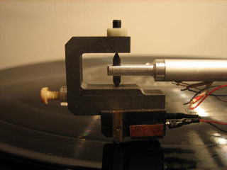
However, I do like its bearing design on the headshell pivot by using two spikes going opposite directions and a "counterweight" to balance the cartridge mass on the axle. We can possibly implement the idea or ideas on a DIY tonearm in the future.
You must be talking about this section:
2. Down force occurs too
An externally hosted image should be here but it was not working when we last tested it.
Offset angle doesn't only exist in horizontal plane. It also exists in vertical plane. As you can see on diagram 1, there's an extra force pulling the arm down. This means that, according to the change of the groove formation, the arm itself goes up and down in relation to the surface of the record, adding modulations to the output of the vertical element which controls the stereo effect.
Since the RS arm is NOT about tangency, I never bother to investigate further into its design nor theory, to be honest. We just have to move on . . .
- - - - - - - - - - - - - - - - - - - - - - - - - - - - - - - - - - - - - - -
However, I do like its bearing design on the headshell pivot by using two spikes going opposite directions and a "counterweight" to balance the cartridge mass on the axle. We can possibly implement the idea or ideas on a DIY tonearm in the future.
Since the RS arm is NOT about tangency, I never bother to investigate further into its design nor theory, to be honest. We just have to move on . . .
Certainly, RS-1 isn't made for tangency. Been unfortunate enough for not completely forgetting the remnants of school maths, I've tried to make some simple calculations. Here are some funny results:
1) Lateral angular mistake of RS-1 makes about 11,5 degrees at the beginning of first track, and about 10 degrees at the end of last track, on average LP. So, as for angular mistake, RS-1 is a champion among the arms, those created for at least during last 60 years. However, because of unusual location of pivot as well as no overhang, RS-1 really has much smaller side forces induced (comparing with most average arms featuring overhang), and for the first 2/3 the side force goes inside, for the last 1/3 -outside.
2) RS-1 has its pivot point lifted about 68mm above the record-stylus contact point. Average record may have up to 2mm warps, due to record industry standards. The more arm horizontal pivot point is elevated, the more stylus moves back and forth along the groove, while climbing warps, thus bringing speed fluctuations. For RS-1: for 2mm warped 1-st record track, longitude of stylus movements is 0,54 mm for each turn, which gives us speed fluctuations of 0,36%. That is about 4 times more, than with most of average pivot arms. So, here is no free lunch too.
3) As to the pivoted headshells, said to decouple stylus-cartridge vibrations from the tone arm, it seems questionable if it serving that purpose due to the headshell rotation. Pivot point located on the same vertical axe with stylus point should work the same way, as rigid cartridge mount, and not been able to decouple lateral stylus vibrations by rotation. It seems, if it does decoupling, it should be done the same way usual spikes do.
IMHO. If RS-1 really sounds so good (and I've heard it, and with Shilabe cart. it sounded good), as hi-fi reviewers claim, maybe it is not because it works exactly the way its designers intended.
Good news for us is: arms and cartridges may sound good, despite their manufacturers (consciously or not) have ignored some pretty serious technical issues...
Certainly, RS-1 isn't made for tangency. Been unfortunate enough for not completely forgetting the remnants of school maths
, I've tried to make some simple calculations. Here are some funny results:1) Lateral angular mistake of RS-1 makes about 11,5 degrees at the beginning of first track, and about 10 degrees at the end of last track, on average LP. So, as for angular mistake, RS-1 is a champion among the arms, those created for at least during last 60 years. However, because of unusual location of pivot as well as no overhang, RS-1 really has much smaller side forces induced (comparing with most average arms featuring overhang), and for the first 2/3 the side force goes inside, for the last 1/3 -outside.
2) RS-1 has its pivot point lifted about 68mm above the record-stylus contact point. Average record may have up to 2mm warps, due to record industry standards. The more arm horizontal pivot point is elevated, the more stylus moves back and forth along the groove, while climbing warps, thus bringing speed fluctuations. For RS-1: for 2mm warped 1-st record track, longitude of stylus movements is 0,54 mm for each turn, which gives us speed fluctuations of 0,36%. That is about 4 times more, than with most of average pivot arms. So, here is no free lunch too.
3) As to the pivoted headshells, said to decouple stylus-cartridge vibrations from the tone arm, it seems questionable if it serving that purpose due to the headshell rotation. Pivot point located on the same vertical axe with stylus point should work the same way, as rigid cartridge mount, and not been able to decouple lateral stylus vibrations by rotation. It seems, if it does decoupling, it should be done the same way usual spikes do.
IMHO. If RS-1 really sounds so good (and I've heard it, and with Shilabe cart. it sounded good), as hi-fi reviewers claim, maybe it is not because it works exactly the way its designers intended.
Good news for us is: arms and cartridges may sound good, despite their manufacturers (consciously or not) have ignored some pretty serious technical issues...
Last edited:
As the linear speed (and so the same signal lengh in the grove) reduce itself as the diameter of the grove decrease, to equalize distortion, the angle error has to be less in the end of the record than at the beginning. if i remember well we have to optimize Angular mistake/diameter all over the surface for the best result.Lateral angular mistake of RS-1 makes about 11,5 degrees at the beginning of first track, and about 10 degrees at the end of last track,
As a sound engeneer, crying when i listened to my mix on the sample vinyls, with no difference (or so few) on a CD, yes, for sure. But i believe interest in those analog playing machines is for fun, nostalgia, and sometimes, intelligence of the design.No respect is earned until it can sound better than a CD player!
Those machines to play vinyls are often pure beauty by themselves. And, often the sound they deliver is very poetical and nice; letting a great place to the imagination's listener even on bad recorded sources ;-)
Well, sometimes, i really dream to change back my modern car and all the GPS of the world for a long trip with a 20 years old blonde all along th road 66, with the brand new Pink Floyd (more) album on the vacuum tube auto radio.
Last edited:
This thread finally got some respect!
No respect is earned until it can sound better than a CD player!
Strange posts gentlemen
- Home
- Source & Line
- Analogue Source
- Angling for 90° - tangential pivot tonearms