I wanted to verify to be sure, but no, i was right (or you wrong). No convergence at all.No that's not true. DDs supposition is correct, the geometry is a variation on the Birch geometry.
Attachments
To be more precise, the only convergence point is where it is supposed to be: at the vertical of the record's axe. This may-be look like the Birch design, but, in fact, has nothing in common.
And the only errors will depend on the error detection accuracy: can be done less than 0.025°/cm, less than the geometrical error due to the accelerations of the groving machine on high transients. > 20 times better than conventional bent arms. Like any chariot radial arm system.
More images here.
And the only errors will depend on the error detection accuracy: can be done less than 0.025°/cm, less than the geometrical error due to the accelerations of the groving machine on high transients. > 20 times better than conventional bent arms. Like any chariot radial arm system.
More images here.
No that's not true. DDs supposition is correct, the geometry is a variation on the Birch geometry
I wonder why some people on forums can be so affirmative, specially when they are wrong ;-)Thanks for pointing out the geometric relationship
Last edited:
Easy to make you own drawing. Do not need any precision to demonstrate. It is not a question of "trust", try-it and make your own evidence.Possible but I doubt it, I think it's more likely that your drawing is insufficiently accurate. The line spacings appear to vary randomly which doesn't inspire trust.
It is not an actual project ;-).Do you have the actual dimensions at hand?
You can fix the dimensions as you like. That the beauty/simplicity of the idea. Just play with it to understand.
It will work with the Birch's dimensions, i presume, but it is only one figure.
The only limitation is the minimal size of the diameter of the arm plate support.
Dimensions are very different between my images. All are working.
On one of my ruff drawings, diameter of the secondary plate is ~ 54mm, the distance between the plate axes ~190mm , the arm length will be ~152/153 mm. Just tune it for it makes a strait line with his plate axe when tangential at the inner grove. Even that is not critical and can be compensated by the tracking error system.
OK, that's an interesting case, you appear to have designed to minimise the radius of the "chariot" disc. As per DDs comments above, this maximises the relative length of the second arm (segments DC in our constructions) and moves us further away from the Thales circle.
Accordingly, the fit to Birch geometry is quite poor. For PD = 28, DC = 155 and AP = 190*, I get a Thales locus at 235 mm and a maximal error of 0.6 mm which should correspond to a tracking angle error of about 0.4 degrees. Increasing the "chariot" radius by a few mm so that it's a straight line at zero radius decreases the maximal error to 0.2mm.
*These dimensions are as close to your geometry as I can enter into my spreadsheet without generating divide by zero errors.
Last edited:
Indeed.OK, that's an interesting case, you appear to have designed to minimise the radius of the chariot disc.
Well, notice my quick'n dirty design was for a 110mm groove minimal diameter. You better chose 108mm for 45rpms compatibility .
A safe design solution solution would be to set the arm making a strait line with the plate diameter at inner groove, and tangential with his plate support when diamond is on the outer groove. Making the arm plate diameter around 64mm and the arm length to 162mm witch brings the distance between axes to 201.37mm. But some can play to minimize further the arm plate size.
I would like to insist on that, as long exists a solution both on the outer and inner groove for the arm to be tangential, there will be no angle error in between with the servo system, else than the servo's precision itself. So, we do not have to worry about.Increasing the "chariot" radius by a few mm so that it's a straight line at zero radius decreases the maximal error to 0.2mm.
Last edited:
Not to be picky, but this chariot idea has an optomechanical feedback mechanism yes? This is a deviation from the purely mechanical system desired by this thread... But thats why I like it. I see a complication arising from having the optical pickup being located at the record spindle. How do you resolve this difficulty?
The Shroeder LT design seems to replace the need for feedback with a magnet and a a rail. I like the elegance, but worry about the stiffness of that system.
Thoughts?
The Shroeder LT design seems to replace the need for feedback with a magnet and a a rail. I like the elegance, but worry about the stiffness of that system.
Thoughts?
As i said, it is not supposed to be mechanical, a servo is less expensive, less complicated to design and DIY, and keep-you away from errors. The geometry is not complicated, a second pivot and a plate.I agree mechanically it's simpler to rotate a plate than it is to glide on a track and it's easier to install because of the smaller footprint but it complicates the geometry more than I would like. However, if it's a purely mechanical design then we're really on to something...
But, if you are about a purely mechanical thing on the same geometry: attached a schematic. Just replace the servo with a secondary articulated arm between the Diamond axis and the point Z, and you'r done. The two articulated arms can be under.
I think that, if any error, it will be very minimal (No error when servo).
Attachments
Last edited:
We've gone around in a circle (yes, that was intentional)
Your "Diamond Axe" is actually the centre of the Thales circle. The errors depend on the relative dimensions of the arms.
The errors for the case you posit (designed, as you said, for a servo) and for a version which works better passively are in post #245. To eliminate the errors one of the circles in your diagram must be replaced with a non - circle, for example an arm whose length (radius) varies.
We've gone around in a circle (yes, that was intentional)
In fact, since 3 decades, i'm much more interested in DAC than vinyls.
It is like designing saddles for dinosaurs.
Just fun to remember the good old days.
Last edited:
Please, can-you provide a comprehensive design (means where you can see at first look what is each point for, as mine) with numbers ?Your "Diamond Axe" is actually the centre of the Thales circle...(snip)
...The errors for the case you posit (designed, as you said, for a servo) and for a version which works better passively are in post #245. To eliminate the errors one of the circles in your diagram must be replaced with a non - circle, for example an arm whose length (radius) varies.
You are talking of the Thales arm, and i don't see the relatioship: they are not strait arms. And i don't understand your "non circle".
I propose Pivot axes, and fixed length arms.
If you have a calculation method, it would be interesting to publish-it in the same post.
BTW: Error angle is not the interesting thing to minimise, but the distortion it produce: Means 'error angle'/'distance from the record center'.
Regards.
I already have, in posts #219 and #222. Change the numbers as you require.
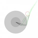
To understand the relationship, take your last drawing and extend the arc centred at Z to make a semicircle from the spindle. This is the equivalent Thales semicircle.
Now extend all the green lines backwards to their convergence. They should approximately converge at the opposite vertex of the semicircle.
The degree of non convergence can be used to estimate the error angles.
Last edited:
How can-i explain, 'without to gone around in a circle ;-)', that, in my design, they do not converge ? At all. I'm outside of your Thales figure.They should approximately converge at the opposite vertex of the semicircle.
.
And, however, the error angle (if mechanical) is very minimal, less than any classical arm, mostly situated in the first1/3 of the record, nothing to worry about as you can see in my last draying.
EOT for me, i will not spend my life to argue, i posted this just to share an 40 years old patented idea of mine if it can help. Feel free to improve-it.
Hello Christophe,
Please provide the patent number.
Sincerely,
Ralf
i posted this just to share an 40 years old patented idea of mine.
Please provide the patent number.
Sincerely,
Ralf
My god ! It is 40 years old, and the patent was deposed by the company lawyer, not me (i was just an employee). Name of the company was "Scientelec". Patented in France around 1972.Please provide the patent number.
How can-i explain, 'without to gone around in a circle ;-)', that, in my design, they do not converge ? At all. I'm outside of your Thales figure.
You can't, because it isn't true.
You admitted it yourself by drawing the arc through the stylus loci. This arc forms part of a Thales circle. Your particular circle misses the spindle by about 3mm but that's simply a matter of accuracy. The distance from the spindle may be used to estimate the errors which as you say are less than for a normal pivoted arm. A small modification (increasing the diameter of the "chariot" by a few mm) reduces the errors greatly.
There's no substitute for geometry.
BTW your design won't work at all as a purely mechanical arm as stylus drag will force the chariot to rotate until the forces on the arm balance.
Last edited:
"I see a complication arising from having the optical pickup being located at the record spindle. How do you resolve this difficulty?"
Good question. I am still trying to figure out how Esperado's design detects tangency. It appears there has to be some form of laser or sensor system located at the spindle area but how it is implemented is the question. Perhaps I didn't read careful enough of his comments. Care to elaborate?
As I said earlier, I like the design's smaller footprint but it creates unnecessary geometric complication. A Rabco style tonearm may not be the simplest design but at least it's simple to understand...
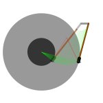
A little drowning is better than thousand words.Good question. I am still trying to figure out how Esperado's design detects tangency. It appears there has to be some form of laser or sensor system located at the spindle area but how it is implemented is the question. Perhaps I didn't read careful enough of his comments. Care to elaborate?.
To sense the laser diode, this kind of thing could be perfect.
But you can think instead to use a LED, reduce the diameter of the emitted light by a slit and two photodiodes in a Weston bridge to measure.
The sensor has to be situated just under the record spindle.
Not very complicated.
Attachments
"The sensor has to be situated just under the record spindle. Not very complicated."
Now I see why it's not complicated to you. It's a rather brute force way of doing it and no wonder you don't care about the geometry on the pivots. Having a laser underneath the record center certainly simplifies the sensor system.
This kind of motorized system is outside of the discussion of purely mechanical system but it is fun to see drawings of it.
More RMAF show report on the new Schröder linear tracking tonearm in 6moons.com's "industry feature" section. And here what the writer has to say about the sound of the new arm.
The writer also awarded the arm as "Best Technological Innovation" at the show. Looks like Frank has another winner!
Now, if only Frank can reveal a little more about the design....")
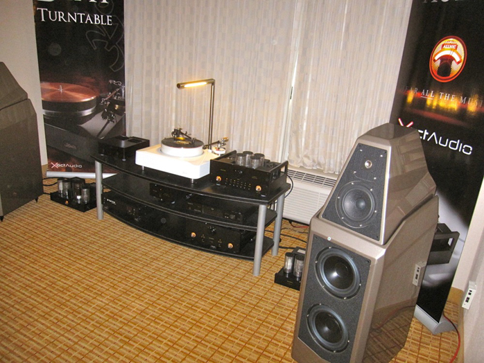
"I got excited just looking at the gorgeous Kodo Magdrive turntable! Top it off with a Reed tonearm and the debut of the new Schroeder linear tracking tone arm! I was about to burst at the opportunity to hear this demo. The Schroeder arm has an ingenious mechanism whereby the pivot point of the arm mounted on a cam is pulled out in an arc by the stylus to achieve tangency. The ever-cordial Steve Dobbins provided us with a demo of the two arms playing the same cut both with an Allnic Puritas cartridge (broken in by the same amount of time). Dexter Gordon was the selected record. The Schroeder arm was more relaxed, had more body and better bass. There was a very noticeable difference on the trumpet climax and when the sound got complex, the top end of the Schroeder was just sweeter. This demo was one of the highlights of the show for me." --Steve Marsh
The writer also awarded the arm as "Best Technological Innovation" at the show. Looks like Frank has another winner!
Now, if only Frank can reveal a little more about the design....
An externally hosted image should be here but it was not working when we last tested it.
- Home
- Source & Line
- Analogue Source
- Angling for 90° - tangential pivot tonearms