Pro and cons? I'm just starting this OB adventure. I would suspect the biggest advantage is crossover point of sub. I not shure I'm going to use a sub with mine. If is did I would guess it would be around 50 to 80 hz. The B200 go as low in OB as the fe206e in MLTL, and with more athority in the midbass.
I've have read the high Qts drivers dont have the same acuracy in the upper freq., but the B200 are at least as detailed as the fe206e.
Chris
I've have read the high Qts drivers dont have the same acuracy in the upper freq., but the B200 are at least as detailed as the fe206e.
Chris
>Martin
Can you eleborate more on this? Is there any specific reason you like low Qts drivers more then high ones?
Bartek
I like low Qts drivers and there is no EQ other then the volume boost.
Can you eleborate more on this? Is there any specific reason you like low Qts drivers more then high ones?
Bartek
MJK said:
What advantage do you believe a higher Qts driver will produce? What disadvantages? I think everythign is a trade-off.
Thorsten (aka Kuei) sums it up pretty well here:
http://www.diyaudio.com/forums/showthread.php?s=&threadid=19883&perpage=10&pagenumber=3
Doesn´t that work like a U baffle with a lambda/4 resonance to the open back of the "box"?
I remember increasing "boxiness" with my winged open baffles, when I folded the wings back until the angle between them became less than 60°.
I don't know the answer to your question with any proven math or modeling, but here is my impression of the potential for standing waves in the cavity created as shown in your sketch and used in my design.
The two open sides, the back and the top, have in a simple form a boundary condition that requires the pressure to be equal to zero. So if a quarter wavelength standing wave exists in the vertical direction, the pressure has to diminish in magnitude so that at the very back it is zero everywhere along the back opening. If a quarter wavelength standing wave exists from front to back the pressure must diminish in magnitude to be zero along the top opening. A half wavelength standing wave between the two sides needs to diminish so the pressure along the back and top is zero. With those kinds of restrictions on the pressure profile in any standing wave. it would be maximum near the bottom along the front baffle in the corner formed with the floor.
The next point it to look at what frequencies of standing waves might exist.
1/4 wave from bottom to top
f = c / (4 x 48 inches) = 71 Hz
1/4 wave from front to back
f = c / (4 x 12 inches) = 282 Hz
1/2 standing wave between the sides
f = c / (2 x 24 inches) = 282 Hz
The first frequency at 71 Hz is in the range where the woofers are playing so I guess one could posulate it might be excited if combined with another pressure profile that summed to produced zero at the back opening.
The other two frequencies are a little harder to convince myself they exist. The excitation is coming from the Lowther which is near the top and centered, so the coupling is weak with both mode shapes.
This is my thinking about why I am not worried about standing waves in the cavity formed by the front and two sides. I have seen this claim posted before and have to wonder how much is fact and how much is pure speculation stated as fact. I am more concerned about exciting vibration or motions of the panels in reaction to the woofer motions.
Can you eleborate more on this? Is there any specific reason you like low Qts drivers more then high ones?
Restating the question and having read the referenced post by Thorsten, I'll offer the following comments for discussion. These are my thoughts and by no means should they be the final word on anything, I am still learning.
I agree that a higher Qts driver performs better in an infinite baffle. I would also add that this is true if the driver is being used over an extended frequency range where the response above fs is being used. But my design idea is a little different for this speaker.
The Lowther drivers have low Qts due to the large magnet's strength which produces higher SPL.
PM2C = 97.0 dB/w/m
PM2A = 97.4 dB/w/m
DX4 = 98.1 dB/w/m
The Dayton woofers have a Qts of 0.37, a fs of 39.5 Hz, and an efficiency of 97 dB/w/m. A single Dayton woofer was not going to do the job in an OB paired with any of the Lowthers. So I used two wired in parallel and boosted the SPL even more using the digital crossover. So now the low frequency pair of drivers are much more efficient then the Lowthers. Then by selecting a crossover point between 100 and 200 Hz, and rolling the Daytons off at 12 dB/octave, I produced a almost symmetric hump like SPL response. Adding this to the Lowther, crossed over at 24 dB/octave, produced a flat combined response that went down into the 30 Hz to 40 Hz range depending on the crossover settings. This is not a minimalists approach and it does not use the drivers at an optimum condition, but I think the results work. It is a wasteful design by some people's rules just like my Lowther and BSC ML TL design.
I like low Qts drivers because they typically have big magnets and are very efficient. You can increase the effective Qts by adding series resistance tailoring the system SPL response. It is easy to increase the effective Qts of a driver but not so easy to reduce the Qts of an already high Qts driver. There is a lot of adjustment that can be done on a low Qts driver from the system level. Again, this goes against the typical use of Lowthers and some Fostex drivers and it is wasteful of the high efficiency in the raw driver. Guilty of non purist thoughts! But I believe it produces a very high quality speaker design, others might argue and they are welcome to approach the problem differently.
MJK said:1/4 wave from front to back
f = c / (4 x 12 inches) = 282 Hz
1/2 standing wave between the sides
f = c / (2 x 24 inches) = 282 Hz
...
The other two frequencies are a little harder to convince myself they exist. The excitation is coming from the Lowther which is near the top and centered, so the coupling is weak with both mode shapes.
MJK,
thanks for your detailed derivation. That 282 Hz is just in the range of resonance many H baffles have to cope with. And those resonances do exist:
http://www.linkwitzlab.com/models.htm#C
You state that you are crossing the Daytons between 100 and 200 Hz, and rolling off at 12 dB/octave. Taking you are crossing @150 Hz and the resonance peak is 9 dB high, that peak would still lurk with -3dB at 282 Hz, if not compensated.
I don´t say that this has to be detrimental to your design. I just was wondering whether those side panels in your OB design do serve any intended acoustic purpose.
Rudolf
That 282 Hz is just in the range of resonance many H baffles have to cope with. And those resonances do exist
I agree, but isn't his H baffle closed at the top? If it is then he has two short TL's and the resonances at 282Hz are a real concern. I did some work for John K modeling H and U baffles a few years ago and this is indeed what happens.
But if the top is left open then I am not sure that this resonance will be excited nearly as strongly, if at all, and the response peak will be much lower. The open top and back are the key variables that will determine what resonances exist in the cavity formed by the baffle and two sides.
MJK said:I agree, but isn't his H baffle closed at the top?
Indeed they are. Not that the Orion is a bad speaker of course (I know you're not implying that, I hasten to add)... in fact, they are the best I've ever heard, from anything, and so they should be, cosidering the fact that they are far, far out of my price range, though very reasonable for what they achieve. Doesn't mean they can't be improved upon of course -I wonder what SL would think of your new MathCad OB worksheet once it's released -he's always looking for new ideas and ways to improve things. Perhaps we could tempt him onto the forum.
Best
Scott
MJK said:But if the top is left open then I am not sure that this resonance will be excited nearly as strongly, if at all, and the response peak will be much lower. The open top and back are the key variables that will determine what resonances exist in the cavity formed by the baffle and two sides.
Martin,
thank you VERY much for that statement. I know I should have ripped the tops off my H baffles and measure the change by myself, but I´m the guy who needs enforcement by theory to do the obvious in real life.

Let´s see who is first with published data: your FEM model or my measurements of a ripped H baffle.
Rudolf
I am sure you will be first, my backlog of interesting stuff to do is huge.
If you rip the top off of your H frames, are you going to be left with a woofer in a very small baffle? I wonder if the 1/4 wave resonance, and effective distance betwwen the sources, is what helps produce the bass. If the baffle is small you may eliminate your objectional resonance at the expense of your bass output.
If you rip the top off of your H frames, are you going to be left with a woofer in a very small baffle? I wonder if the 1/4 wave resonance, and effective distance betwwen the sources, is what helps produce the bass. If the baffle is small you may eliminate your objectional resonance at the expense of your bass output.
Well, my current baffles actually are Z baffles.
What I will do is: build a provisional real H baffle with the same drivers (10") and same outer dimensions where I can screw the top on and off. That way I can see exactly to what extend I "eliminate your objectional resonance at the expense of your bass output".
What I will do is: build a provisional real H baffle with the same drivers (10") and same outer dimensions where I can screw the top on and off. That way I can see exactly to what extend I "eliminate your objectional resonance at the expense of your bass output".
Attachments
In the case of your current Z baffles, you might loose some, (assuming that there is some loading going on), but probably not as much as with the drivers mounted vertically on an H baffle. In the Z, it looks to me as if you're going to get a boost from the floor-boundry condition, so the loss of the top might not be quite as significant. Just my tuppence worth.
Best
Scott
Best
Scott
Scott,
I see your argument.
The Z baffle without the top will behave even more unsymmetric and unpredictable than it does already. So results would be arguable. That´s why I will do a "formal" H baffle, hoping to get a better insight. Got some chipboard in the basement and hope I can find some time there too.
If other parameters could be kept unchanged, the low damped drivers (high q) are better for an OB regarding only the low freq cut off alone, since a -3dB point at the driver’s fs could be obtained if its Qts equals 0,7, but the problem with one dimension/parameter is that it can’t be changed alone, and there are also other parameters that one has to look after except physical low end extension. As Martin already said, low q also means (it comes with / it is a result of such a design) big motors, low mms and high sensitivity in general.
Q is also related with step response – a driver with a Qt of 0.3 will have a much better step response from a 0.7 one, in an OB alignment. Part of what is perceived as ‘quick, precise and without coloration bass’ in open baffle designs (another part comes from in box standing waves that pass through the cone material, and the smallest part comes from box construction resonations, as I believe) is a result of the lack of a resonating air volume which in every case worsens the driver’s free air step response (step response is depended on the driver/enclosure Q, which in the case of the OB is at about the driver’s Qts, and in the case of a box it is always bigger). If OB is used with a driver of 0,7 Qts then the resulting step response is even worse than that of a 0.3Qts driver in a closed 0.6Q system enclosure. Lastly, part of what is sometimes perceived as ‘thin bass’ in some circumstances is exactly because of a very low total Q and a resulting very high, subjectively ‘not physical’ damping, and perhaps extremely low Qts drivers should not be used in OB – but a value of about 0,4 as used here is a good compromise, I think.
So Martin just ads another woofer and gets his desired low frequency response and a better defined bass together with drivers adequate to extend well and also gets micro-details and micro-dynamics which also come with a low cone mass material and good motor, as well;-) As always, it is about tradeoffs and personal demands and likings.
Regards,
Thalis.
I promised to do some measurements to look after the effect of pulling off the top cover from a H baffle.
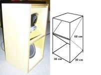
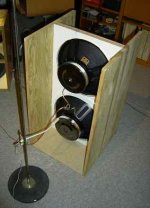
First a picture of the assembly:
It shows two 15" drivers in a H frame of 82 cm height and 40 cm inner width. Depth is 20 cm in the back and 22 cm in the front.
I did measurements with the mike in the center of the back plane, 20 cm from the loudspeaker baffle.
The top cover was split in two halfs. One covering the front top and the other one covering the back.
Attachments
For MJK primarily:
The red line in the diagram shows the H baffle with the top cover on. Black line is with the back part of the top cover lifted off. It´s hardly recognisable, because the green line, showing both covers lifted off (as in the photo) is at almost the same position.
What I see is, that removing the top of a H baffle doesn´t change the character of the baffle much (in this assembly).
I know that I have to do some more measurements to complete the picture. So what measurements should I do next? I will have to confine measurements to the nearfield for the next sessions, so please don´t ask for more than 1 m distance.
BTW: SPL levels are not calibrated, but the mike is.
Attachments
What I see is, that removing the top of a H baffle doesn´t change the character of the baffle much (in this assembly).
I agree. And to take it one step futher, there cannot be any standing waves between the sides of the baffle in any of the measurements because changing the end condition would have had an impact on the mode and the SPL response. So I conclude that in the frequency range you measured, I would not be worried about standing waves impacting the sound. This could also be checked by plotting the driver impedance where a standing wave would appear as a discontinuity (wiggle) in the amplitude and phase.
- Status
- This old topic is closed. If you want to reopen this topic, contact a moderator using the "Report Post" button.
- Home
- Loudspeakers
- Full Range
- And now for something completely different ......