
This thread is now a Sticky for you all to post pictures of your Analogue Line Level diy efforts and projects.
Please try and keep the thread on topic and take any technical discussions over to either a new discussion thread or the original thread if there is one.
Is there one? I can't seem to find it. Is it possible to get one?
Here's a contribution to perhaps get one going.
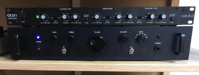
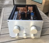
A recent pre-amp build that’s also somewhat of a milestone for me since it’s project that started a very long time ago in the 90’s and was repeatedly shelved and restarted for various reasons. Some aspects of design remain as originally planned and use parts acquired in the 90’s such as the Linear Tech ICs, transformer, case and knobs. A few updates modernize it a bit with remote volume control, Bluetooth and digital inputs.
It’s a simple op-amp based pre-amp with:
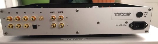
1) 3 analog line level inputs
2) 2 digital inputs – optical and coaxial with built in DAC
3) 1 Bluetooth input
4) IR remote for volume control via motorized pot
5) Tone Controls +/- 10 dB - switchable
6) Headphone amp
Other features -
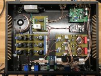
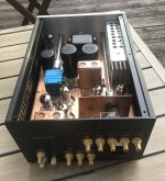
AC line EMI noise filter
Torroidal power transformer
LT1033 / 1085 based regulated power supply, +/- 15V, and +12V
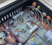
LT1056 JFET input op-amps
LT1010 buffered output and headphone driver
ESS9038Q2M based DAC
All internal signal wires individually shielded with teflon RG-178 coax
Front panel from Front Panel Express
Purchased modules were the DAC, Bluetooth receiver and the IR remote volume control.
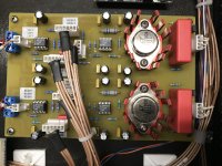
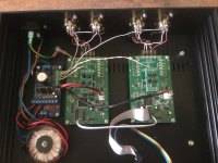
The power supply, time delay board and main pre-amp board are my design and hand made with old school toner transfer and etch methods.
It works well, sounds great and gets daily use in my main system. Well worth the wait.
Here's a contribution to perhaps get one going.
A recent pre-amp build that’s also somewhat of a milestone for me since it’s project that started a very long time ago in the 90’s and was repeatedly shelved and restarted for various reasons. Some aspects of design remain as originally planned and use parts acquired in the 90’s such as the Linear Tech ICs, transformer, case and knobs. A few updates modernize it a bit with remote volume control, Bluetooth and digital inputs.
It’s a simple op-amp based pre-amp with:
1) 3 analog line level inputs
2) 2 digital inputs – optical and coaxial with built in DAC
3) 1 Bluetooth input
4) IR remote for volume control via motorized pot
5) Tone Controls +/- 10 dB - switchable
6) Headphone amp
Other features -
AC line EMI noise filter
Torroidal power transformer
LT1033 / 1085 based regulated power supply, +/- 15V, and +12V
LT1056 JFET input op-amps
LT1010 buffered output and headphone driver
ESS9038Q2M based DAC
All internal signal wires individually shielded with teflon RG-178 coax
Front panel from Front Panel Express
Purchased modules were the DAC, Bluetooth receiver and the IR remote volume control.
The power supply, time delay board and main pre-amp board are my design and hand made with old school toner transfer and etch methods.
It works well, sounds great and gets daily use in my main system. Well worth the wait.
Attachments
Hi!
Thanks.")
Some time ago I "inappropriately" posted my build with fewer pics in "analog-line-level" due to the lack of this section
I'll just put it back here:
RS-PA3 : PreAmp, completely Reed switched ( same on my own site, more detailed: )
Volume control by step switches, which as well as the input selector switch are represented by reed contacts. The reed contacts are actuated by permanent magnets.


After that I had already searched in vain. But I think now we have it.Analog Line Level Photo Gallery
Is there one? I can't seem to find it. Is it possible to get one?
Here's a contribution to perhaps get one going.
Thanks.
Some time ago I "inappropriately" posted my build with fewer pics in "analog-line-level" due to the lack of this section
I'll just put it back here:
RS-PA3 : PreAmp, completely Reed switched ( same on my own site, more detailed: )
Volume control by step switches, which as well as the input selector switch are represented by reed contacts. The reed contacts are actuated by permanent magnets.
- LINE amplifier with 2 x OPA27 per channel
- RIAA stage based on SUPRA 1 (6/7 Elektor 1982)
- No balance control: different volume setting of the channels possible by mechanically independent controller, which are operated simultanously.
- tape (monitor) switched on/off by pressing or pulling the input selector knob
- Inputs: Phono,Tape-in/out,CD,Tuner,Aux1,Aux2
The two different units shown.
Have a question, perhaps due to the absence of a complete under the hood pic: how do you read the attenuators position?


Thank you!This thread is now a Sticky for you all to post pictures of your Analogue Line Level diy efforts and projects.
Please try and keep the thread on topic and take any technical discussions over to either a new discussion thread or the original thread if there is one.
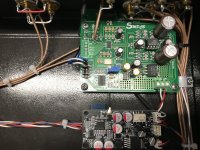
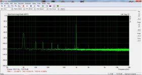
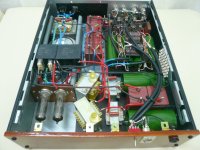
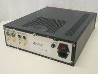
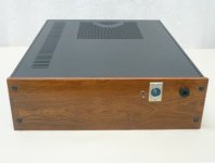
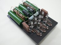
Here is an hypochondriac project... Full dual psu, differential in/out and very high gain, originally built to be the analog buffer of my DAC in the early days of its evolution. What you see here is 100mV in to 1,9V out. It can do headphones too but not the very low impedance. I put all my effort to make it noiseless. The tubes are on a piece of wood that stands on rubber feet for HDD. Same approach for the sub chassis that holds the transformers and rectifiers. Al put in a repurposed PC case. Mostly foil capacitors and chokes rewounded at home to match the values I found in PSUDII for a ripple and ringing free psu. I think I'm close to target given that the heaters' supply is pure AC. Yet to try a small SMPS I already have to see if I could eliminate those spikes at the lower frequencies.
Attachments
Thank you George! It looks better in the pictures.
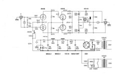
Schematic is accurate for one channel. Double for stereo including the psu. In total 2x 6n16b double triodes, 4x 4s31b single triodes and 2x ez81 rectifiers.
EDIT: Scematic doesn't show silver mica bypass caps on tube anodes and output caps.
Schematic is accurate for one channel. Double for stereo including the psu. In total 2x 6n16b double triodes, 4x 4s31b single triodes and 2x ez81 rectifiers.
EDIT: Scematic doesn't show silver mica bypass caps on tube anodes and output caps.
Last edited:

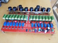
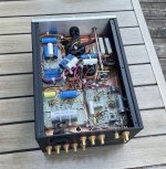
Heres pass p 1.7.
Brass heatsink, distributes heat equally, original Harris irf610, itt relays, siemens 0.1% resistors bought for attenuator but not installed, mkc caps paralleled with Russian petp capacitors.
Think its gonna be a nice preamp with its finished, haven't figured out chassis yet.
Brass heatsink, distributes heat equally, original Harris irf610, itt relays, siemens 0.1% resistors bought for attenuator but not installed, mkc caps paralleled with Russian petp capacitors.
Think its gonna be a nice preamp with its finished, haven't figured out chassis yet.
Attachments
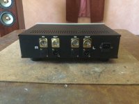
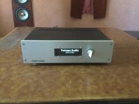
I recently built out my Tortuga Volume Control to be fully balanced.
Case from Modushop, and I had them do the cutouts, printings, and plexiglass insert.
Hookup wire from VHAudio.
Controller boards and psu from Tortuga Audio.
Case from Modushop, and I had them do the cutouts, printings, and plexiglass insert.
Hookup wire from VHAudio.
Controller boards and psu from Tortuga Audio.
Attachments
Member
Joined 2009
Paid Member
I recently finished my Line Amp and Phono Amp, over in the tubes forum:
https://www.diyaudio.com/community/...ndo-ashizawa-m7h-g-1000-ge-10-upgrade.397461/
https://www.diyaudio.com/community/...ndo-ashizawa-m7h-g-1000-ge-10-upgrade.397461/
Attachments
Member
Joined 2009
Paid Member
My old preamplifier, built around 1994 or 1995:
https://www.diyaudio.com/community/attachments/augurkenblik-jpg.1042068/
https://www.diyaudio.com/community/attachments/augurkenblik-jpg.1042068/
- Home
- Source & Line
- Analog Line Level
- Analog Line Level Photo Gallery