Hi
Maybe things can be arranged in such a
way to avoid the cathode bypass cap.
Obviously not simply cutting it, but putting
the 2k res in common in such a way to have
a near no draw current circuit a la Broskie.
Thus preserving the absence of feedback
on the 1th tube (and the gain).
Federico
Maybe things can be arranged in such a
way to avoid the cathode bypass cap.
Obviously not simply cutting it, but putting
the 2k res in common in such a way to have
a near no draw current circuit a la Broskie.
Thus preserving the absence of feedback
on the 1th tube (and the gain).
Federico
Hi,
Hmmm....I fail to see what that circuit has to do with the AN M7.
Other than that, the M7 used the, to my taste, much less dark sounding, 6072.
The cathode of the anode follower wasn't decoupled either.
All in all a classic topology of which all and sundry claimed that the CF sucked sonically....
Cheers,")
Hmmm....I fail to see what that circuit has to do with the AN M7.
Other than that, the M7 used the, to my taste, much less dark sounding, 6072.
The cathode of the anode follower wasn't decoupled either.
All in all a classic topology of which all and sundry claimed that the CF sucked sonically....
Cheers,
Hi!
Fscarpa; I didn't understand very well what You have in mind- my English sucks. You have suggested to remove cathode bypass cap from the first stage if I get this right?
To my information (and I belive the source is good one) Mr. Kondo developed M7 prototype with 5687 anode follower (as in my first stage). Unfortunately this was shown only on few Hi-Fi shows and never came to life. What did came to life is 6072 that You are talking about. Many people think that 5687 anode foll. that was used as a prototype is the m7 preamp- so I have written AN7 prototype-variation.
Cathode follower (second stage) if not made well will sound awfull- so I have thought- why not have first stage as in prototype and second as cathode follower (since I hace 6 pieces of 5687).
I have tried 5687 in anode follower as in first stage and it works o.k. - if I put it as in datasheets than it becomes microphonic. So I thought why not put it as in my first post?!
I would like to drive my bipolar power amplifier (input resistance around 47k).
Hi!
Well sometimes the CF is very welcome. The original line from AN-m7 has the same configuration as schematic above but no bypass cap in cathode of first stage- and mr. Broskie use this kind of circuit with bypass cap in some of it's designs (like in 6dj8 compound preampl).
Well sometimes the CF is very welcome. The original line from AN-m7 has the same configuration as schematic above but no bypass cap in cathode of first stage- and mr. Broskie use this kind of circuit with bypass cap in some of it's designs (like in 6dj8 compound preampl).
Hi sparkle,
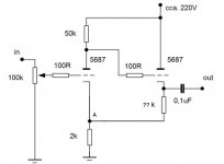
I mean an arrangment like this.
The catode resistance of the 2nd tube
can be selected according to two
different targets.
One can chose to minimize
(to cancel,if possible ) AC voltage
signal at point A ( VA= const., thus making
useless the bypass cap.), or
to minimize AC current drawn from
PSU.
Usually the two conditions
are rather near.
Federico
Attachments
Feedback...not allways negatif...
In your arrangment (as i see it)...you have traded negatif feedback for positif feedback ...
fscarpa58 said:
One can chose to minimize
(to cancel,if possible ) AC voltage
signal at point A ( VA= const., thus making
useless the bypass cap.),
In your arrangment (as i see it)...you have traded negatif feedback for positif feedback ...
sparkle said:
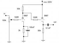
How about one modification of AN7 prototype. Opinions please.....
I would increase the value the output capacitor for something like 0,47uF or more because you are driving a 47K Ohms load...and with your 0,1 uF you will loose bass and will increase the phase shift in the lowest octaves...
Another point is to have a very well smoothed suplly becase this circuit have very low PSRR...
But at the end of the day....i like the circuit...because i like simple circuits...
Good luck!
Hi,
True, but that's not a problem per se. The value of the CF cathode resistor (PFB resistor is you prefer) is very critical to the final outcome.
Cheers,
In your arrangment (as i see it)...you have traded negatif feedback for positif feedback ...
True, but that's not a problem per se. The value of the CF cathode resistor (PFB resistor is you prefer) is very critical to the final outcome.
Cheers,
fdegrove said:Hi,
True, but that's not a problem per se. The value of the CF cathode resistor (PFB resistor is you prefer) is very critical to the final outcome.
Cheers,
Yes...if it was a capacitor ...we can call that a bootstrap circuit...
Of course is not a problem...i only have pointed the issue because of the promise
Thus preserving the absence of feedback
Cheers
sparkle said:Hi!
Tube Dude; I thought it would be the case (with increasing the value fo coupling cap from 0,1uF to 0,47uF). Thanks....
Don't forget to put a high value resistor connecting the right side of the output capacitor to ground...for a path for DC charging at turn on...if not when you connect the interconect to the power amp...Bum!!!..

Good work!
In your arrangment (as i see it)...you have traded negatif feedback for positif feedback ...
It depends
Things may be arranged in such a way to null
the AC current in the grounded resistor (2k).
When this is accomplished there is no more feedback
Federico
But this is accomplished with positif feedback from the output...Yes...there is no negatif feedback in the input circuit (grid - cathode)...but there is positif feedback inside the loop (cathode of the first valve-output of the amp)...fscarpa58 said:
It depends
Things may be arranged in such a way to null
the AC current in the grounded resistor (2k).
When this is accomplished there is no more feedback
Federico
Think that way...if you connect the output with a resistor to the grid of the first valve...you have negatif feedback...if it is to the cathode...is positif feedback...
Cheers
Hi,
Another way of going about it is to stick a grounded grid triode in the tail of the CF and apply positive FB to the cathode of the first stage.
Keep in mind the very high B+ for the to triode so this heater will need to be biased.
An example from a Jean Hiraga preamp that I know to sound very good:
Cheers,
Attachments
My own:
E80CC with 100k load and 2.2k cathode, unbypassed.
6201 (ECC81) grid to E80CC without stopper and 22k cathode.
Coupling cap out 3.3uF and a 1Mohm to ground.
Volume control an Alps 100k.
B+ 250V.
In my case I have another CF before the volume control, it's a bootstrapped CF using 6201. Input impedance many Mohms
)...but there is positif feedback inside the loop (cathode of the first valve-output of the amp)...
I have to disagree
When point A is at virtual ground
for AC the first tube does not see
the output tube
period
Federico
Hi,
Jan,
Do you mean a White CF?
Federico,
I agree.
Cheers,
Jan,
In my case I have another CF before the volume control, it's a bootstrapped CF using 6201.
Do you mean a White CF?
Federico,
When point A is at virtual ground for AC the first tube does not see the output tube period
I agree.
Cheers,
fdegrove said:Do you mean a White CF?
No, just a 6201 with 1.5k + 47k cathode resistors and a 470k grid leak to the junction of the cathode resistors. Input impedance is bootstrapped.
But I do like the White follower somehow, possibly good for driving nasty power triodes
- Status
- This old topic is closed. If you want to reopen this topic, contact a moderator using the "Report Post" button.
- Home
- Amplifiers
- Tubes / Valves
- AN7 prototype- variation?