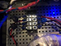
Great advice, thank you! I re did the barrier strip using those. After taking it apart, I realize that had to be the mistake. I tinned the wires and the solder dried in such a way that the contact between the wires and strip was probably very minimal. Now there is much more solid contact.
I fired everything up and it's working great and is dead silent.
Now I just have to check and tune P3.
Thanks!
I fired everything up and it's working great and is dead silent.
Now I just have to check and tune P3.
Thanks!
Attachments
Do you guys just crush these things on? I cant get comfy with that. I grab the ring with an old pair of large needle nose pliers, stick the plastic end in flame until it begins to catch fire and scrap the plastic off. crush it to wire and solder. Then cover with heat shrink.
Russellc
A proper crimp tool is all you need,no reason to solder.
Questions for the more advanced peoples out there:
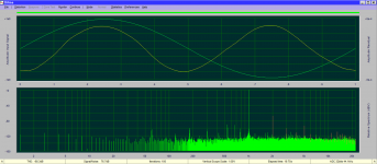
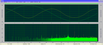
Here are two results from my very basic distortion analyzer set up.
The first picture shows me turning P3 to the left 3 turns.
The second picture shows P3 turned to the right 5 turns.
My uneducated interpretation of the results is that both of these results show a strong dominant 2nd harmonic. Is that correct?
What is the difference between the two results in the top section? Is that the phase or something else? The fundamental is the same but the yellow line starts at the bottom half on one and the top half on the other.
Attachments
both of these results show a strong dominant 2nd harmonic. Is that correct?
What is the difference between the two results in the top section? Is that the
phase or something else?
Yes, the adjustment ranges from in-phase 2nd, to null (none), to out-of-phase 2nd.
Mr. Pass encourages you to listen to the differences, and choose which you prefer.
Last edited:
Thanks for the answers.
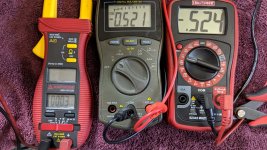
The software is DiAna. I don’t have the software calibrated and fined tuned perfectly, but I think well enough to test for the harmonics.
It’s an interesting delimma with the “ideal” setting. I like it null and with a 2nd harmonic. For different reasons and for different music.
The software is DiAna. I don’t have the software calibrated and fined tuned perfectly, but I think well enough to test for the harmonics.
It’s an interesting delimma with the “ideal” setting. I like it null and with a 2nd harmonic. For different reasons and for different music.
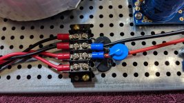
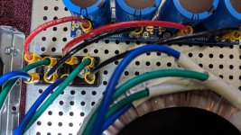
This is a PSA (Pre Smoke Analysis) If someone would take a look at these two pics and let me know if these connections look correct before I energize it, I would REALLY appreciate that!  In the pic with the block rectifier, the + beveled corner is the upper left corner of the block with the red wire attached to it.
In the pic with the block rectifier, the + beveled corner is the upper left corner of the block with the red wire attached to it.Attachments
I already intended to test the PS without anything on the output but thanks for reminding me. I'll get the CL60s off the deck. But with no comment I assume the wires look like they all got to the correct places? What voltages should I expect on the PS outputs initially?
Thanks for all your help 6L6. I've gotten deep into this hobby very quickly. I really appreciate what you, Zen, Nelson, Jason and all the other members have done from me as I stumble through on a wing and a prayer!
Thanks for all your help 6L6. I've gotten deep into this hobby very quickly. I really appreciate what you, Zen, Nelson, Jason and all the other members have done from me as I stumble through on a wing and a prayer!
Dummy needs help please!
F5 is done. I've looked for initial set-up instructions and found several. Some don't make sense referencing only P1 and P2 and no P3 and others just don't make enough sense, to me at least, for me to trust my interpretation. Would someone please direct me to the instructions that are correct for the current version of this amp. I really don't want to smoke this after I've made it this far. Help would be GREATLY appreciated!
F5 is done. I've looked for initial set-up instructions and found several. Some don't make sense referencing only P1 and P2 and no P3 and others just don't make enough sense, to me at least, for me to trust my interpretation. Would someone please direct me to the instructions that are correct for the current version of this amp. I really don't want to smoke this after I've made it this far. Help would be GREATLY appreciated!
This actually makes sense to me as a "paint by numbers" builder... https://www.diyaudio.com/forums/pass-labs/335350-f5-build-11.html#post5770961
Hi Bob,
Please also see my comment here on he initial setting of P1 and P2:
https://www.diyaudio.com/forums/pass-labs/335350-f5-build-12.html#post5771037
Dennis
Please also see my comment here on he initial setting of P1 and P2:
https://www.diyaudio.com/forums/pass-labs/335350-f5-build-12.html#post5771037
Dennis
I have mostly completed an M2X amp, I even bought the Fets, but thought they may be better used in making another amp, such as the F5.
I was planning to bi-amp my speakers with the M2X and the F5. Since the power supplies are the same, I was thinking of making a pair of combo M2X/F5 amps.
Is there a benefit to going dual mono? 300KVA or 400 KVA Antek 2x18V transformer?
I was planning to bi-amp my speakers with the M2X and the F5. Since the power supplies are the same, I was thinking of making a pair of combo M2X/F5 amps.
Is there a benefit to going dual mono? 300KVA or 400 KVA Antek 2x18V transformer?
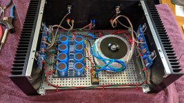
With a LOT of guidance from 6L6 I've managed to get one channel done. I really appreciate his help in understanding this process. Great learning experience for me as a beginner. I also appreciate others adding comments and information. Seems like all the info needed is indeed out there, it is just parsed up enough that without understanding what I was actually doing, I didn't trust it. Makes total sense now.
With the bias at less than .6 the amp is just warm. IR gun showing 110F on the heat sink and 115F on the washer holding the output FETs. Think I'll let it loaf for a while and if I can get the other channel to match it, I'll do some break-in at that bias and keep track of temps. Having fun now!
With the bias at less than .6 the amp is just warm. IR gun showing 110F on the heat sink and 115F on the washer holding the output FETs. Think I'll let it loaf for a while and if I can get the other channel to match it, I'll do some break-in at that bias and keep track of temps. Having fun now!
Attachments

All done and I have a pair of cheap speakers attached for some break-in time before I take (LUG) this thing upstairs. So far it's very quiet but it's not attached to my main speakers yet. The only problem now is the chassis front cover only bolts on with two screws. The bottom two do not align with the rails with the top two in place. Either I am not thinking like an Italian or the front cover is wrong. Anyway here is the final result...
Attachments
- Home
- Amplifiers
- Pass Labs
- An illustrated guide to building an F5