Right, the other channel is behaving normally, I hit 0v offset at .58v bias, and it sounds amazing through my test speakers. Both boards receive the same voltage from PSU.
On the bad channel, only R1 is smoking, and it started once I changed out R12 to a 'good' resistor.
Looks like R1 connects to the input GND, drain of Q1, and R5/R7...
R2 seems to be a happy guy. I saw 17v (!) across R1 before it toasted again on the last power up (3 seconds).
The last power up had R3 at 2.2k, and R4 at 4.7k.
In addition to the bad R12, I also re-used R5-R8 from the board I trashed because of a fully clockwise P1/P2 startup. They are my next suspects, they're the only other pieces that were re-used from that wrecked board. I'm going to lift a leg of each and see what's up, tonight.
Would you try anything other than these next steps ?
- Change R4 back to 2.2k (so both R3/R4 are at 2.2k starting point)
- Change R5-R8 as necessary (possible bad values)
- New Q1/Q2
If I'm still smoking something after these steps, I'll post some images. I'm REALLY ready to hear this thing in stereo. If only so I can listen to it while I populate my BA3+F4 boards!
Flux warts and all... You may notice a very crispy R1, and a front pad lifted from Q3, but it has a solid connection on the rear pad. Thanks for checking it out.
You may notice a very crispy R1, and a front pad lifted from Q3, but it has a solid connection on the rear pad. Thanks for checking it out.An externally hosted image should be here but it was not working when we last tested it.
An externally hosted image should be here but it was not working when we last tested it.
Flick says:
You must be signed in to see this content.
dave
Sorry about that, I've been able to post to the other forums I use with that Flickr account for years. Attempt from Picasa:

This is the better way to post pics, as if anything ever happens with your Flickr account, pics go away. Uploaded to the sight, they are preserved.
Russellc
I did triple-check that Q3 and Q4 are where they should be. Then I checked again after your post. I don't know how to measure MOSFET, but when comparing pin to pin measurements, they compare very closely to the channel that's working.
Looks like Q1, the SK170 BL JFET I pulled, is bad. Would that cause my 17v across R1, though? Or did something blow Q1?
Should I NOT be combining a BL SK170 with the GR SJ74? I had attempted that, based on biasing issues...
Q2
2SJ74 GR
(new)
G to D 8.53k
G to S 8.53k
S to D .03k
(pull)
G to D 8.68k
G to S 8.68k
S to D .04k
Q1
2SK170 BL
(new)
G to D 7.98k
G to S 8.01k
D to S .03k
(pull)
G to D 16R
G to S 13R
D to S 5
Thanks again for any ideas.
Did you also mix GR and BL on your working channel? I don't think it necessarily turns into an issue to mix them, but it might make it more difficult to adjust the bias (your R4 may be insufficient to create sufficient gs voltage for Q4).
My guess would be that you during turn on moved P1 too far away from 0R because you did not see any current and then at some point, Q3 got enough vgs to turn on completely and fried your R1. But that doesn't really explain the broken 2sk170...
My guess would be that you during turn on moved P1 too far away from 0R because you did not see any current and then at some point, Q3 got enough vgs to turn on completely and fried your R1. But that doesn't really explain the broken 2sk170...
The working channel is using GR grade in both Q1/Q2 , and it biased up (with 2.2k R3/R4) eventually after many half turn/check/half turn/check cycles.
I was much sloppier with the channel that's not working, and the scenario you describe certainly could have happened.
There are no visible shorts on the front or rear between pads, no stray wire pieces touching the sink, and the V+,V-,In,Out,GND connections to the board all clear each other as well.
Should I replace the bad Q1 and R1, reset P1/P2 to 0R, and see what happens? Or lift/measure something else on the board before applying power again?
Last edited:
Yes, I think it could be worth a try.
Regarding your active device measurements, ohm measures between pins does not tell you a lot about the device - in many cases it tells more about the polarity of your test probes...
Have a look at this for mosfets:
https://www.passdiy.com/project/articles/matching-devices
And e.g. this for jfets:
http://www.diyaudio.com/forums/pass-labs/228897-jfet-matching-sorting.html
Hey folks.
Finished my f5 tonight and had some biasing issues. Channel one only goes to .3v with zero offset, so I will increase the values of R3 and R4.
Channel two is where the real problem is. My offset at the output exactly matches the bias voltage. I assume that means my mosfet or jfet are toast. Is there a way to troubleshoot the circuit prior to removing both components?
Thanks for the help.
After a few pads lifted during troubleshooting, I went ahead rebuilt a new F5 board for my bad channel. Both channels are now biased and running, and it sounds incredible.
I'm running a Rega RP1 -> boozhound phono pre -> 5687 Aikido into the F5 and it's pushing out some fantastic music.
Cviller, thanks for your input and the great boards.
6L6 thanks very much for all of the shared knowledge across all of your build guides. I've got some F4 and Aleph J boards waiting to get into the chassis next...I hope to have better luck with those.
Hi Guys,
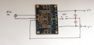
Sorry about asking a question about an F4 on this thread - but I do understand its the same wiring on both amps PSU.
I am stuck with wiring my dual mono F4 with 240v AC mains. Please see pic attached. I am not very good with reading schematic drawings. Also one more question what fuse should I use for the AC?
Transformer specs - 2x24 500 VA - Secondary current - 2 x 10.4 A
Thanks
Dillan
An externally hosted image should be here but it was not working when we last tested it.
I don't know if there is anyone around. Have yet to fire up Peter Daniels F5 boards. Boards stuffed long ago. I'm trying to set trimmer pots to min. Turning them has no effect that i can see. Tried measuring across R5 and R6. No change. Having 4 trimmers behaving identically (2 per board, two boards) leads me to measurement error. If the boards were built following instructions, i.e. pots installed predictably, is counter-clockwise minimum? Thoughts?
Last edited:
If the boards were built following instructions, i.e. pots installed predictably, is counter-clockwise minimum? Thoughts?
Only one is counter-clock. the other is backwards. No, I don't remember which.
Pots installed according to silk screen on board. How much change should I expect to see across R5 and R6 when turning the adj. screw? Attachment placed only because it has picture of unstuffed board showing silk screen. Thanks for the help!!
Attachments
Last edited:
- Home
- Amplifiers
- Pass Labs
- An illustrated guide to building an F5