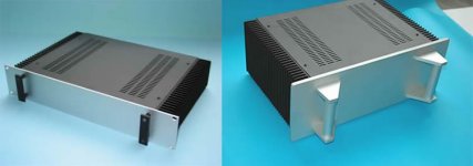
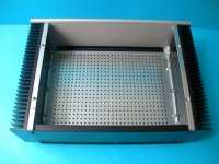
Hi JC,
I'm not Albertob, but if you're looking for heatsinks you might be interested
FRANAB - Industria Metalúrgica Ltda
If you're in SP then they're in your neighbourhood. I bought sinks from them for my F5 a year or two ago and was very pleased the quality of the sinks and the service. I live in Brasilia, so probably like you I can't buy sinks from the places most people on the forum do, because of the shipping cost, but these came out quite reasonably priced.
Regards
Nigel
Hello again Nigel
Yes, you´ve already tipped Franab on another post. I have to leave this project due to others activities.
I found another portuguese forum with interesting F5 case layouts using odd sinks shapes, not sure if efectives though.
First Watt F5 Amp. de Potencia Class A - Página 9
I´m contacting Franab for quotes.
Thanks again, have nice classes and kiss Dilma for me
Abração
Last edited:
Hello again Nigel
Yes, you´ve already tipped Franab on another post....
You're right... I'd forgotten... sorry to repeat myself...
Abracos
Nigel
Faulty memory !
Send it back if it's still under warranty.
In my case it's far too late to hope for warranty coverage... Yesterday I forgot my wedding anniversary...
Regards
Nigel
Last edited:
Alberto, please
Where did you the buy the sinks.
Grácias
Radiateurs - Audiophonics - Câbles, Amplificateurs et Accessoires DIY
I think the shipping will cost you dearly
I've replaced a mosfet and a couple of resistors...
I'm still having a bit of trouble biasing one channel on my F5. I've zeroed the pots. and when I hook up my probes and power the amp on.
I've been getting .352v and 0v to start with... I can tweak each pot. a bit but it seems like i'm always .35v seperation between the right and left sides of the channel.
Any suggestions?
Radiateurs - Audiophonics - Câbles, Amplificateurs et Accessoires DIY
I think the shipping will cost you dearly
Thanks very much for the info:
I also saw these: Hifi 2000 - Boîtier dissipateur 400mm 5U - Facade 4mm at € 215

Silver or black:

They are of Italian origin, I understand
albert
Yup. I'm having the same issue as before.
The mosfet I replaced is the not the one that's causing the issue.
Note: CVILLER wrote he had made a typo on a board. Do you use his board???
I don't have an idea of the difference 000 mv and 350 mv. I understand lef ch and right ch. Or talk about top/noth part of the circuit and bottom /south part of the circuit.
(Talking N/S is what I learned at telecoms
My preferred startup procedure is the following:
I check the output and input tranies are wired OK.
Then:
1)
turn the drain resistors to zero on the input
take out the gate resistors.
Turn on and measure the voltage at the drain at the input pairs; when you turn the resistor, it should slowly come up from zero to 3-4 volt below the rail. Repeat top (north part) and bottom (south part).
This assures a correct entrance.
2)
replace the gate resistors
return the drain resistors to zero
take out the two current limiting transistors or just the collector pins. (see 'alternative down under).
Attach an amperemeter to the output.
Turn the beast on (ouch),
then on one side (eg top one) dial the resistance such that current starts to flow. There is a sharp 'knee', below which there is no current and above which it sstarts to flow.
It can only go to the currentdump (the meter). settle it at about 100 mAmp.
Then slowly start to increase the current on the south side side. (the negative rail that is) by increasing that setting.
If this works, then you have the current limiter that is at fault.
Additionally or alternatively:
Instead of connecting the collectors of the limiter transistors Q3/4 to the gate, you can attach them to a led via a 1k2 - 2 k resistor to earth. The led will not light. If it does, there is a wrong circuite here.
2)
replace the gate resistors
return the drain resistors to zero
take out the two current limiting transistors or just the collector pins. (see 'alternative down under).
Attach an amperemeter to the output.
Turn the beast on (ouch),
then on one side (eg top one) dial the resistance such that current starts to flow. There is a sharp 'knee', below which there is no current and above which it sstarts to flow.
It can only go to the currentdump (the meter). settle it at about 100 mAmp.
This is exactly how many people have burned their F5's.

Triode_al, I am sure you can do this without getting into trouble, but only because you know what you are working with. However many tend to turn on top side too much before attending to the south side because the current-flow only starts when both mosfets are conducting. So when you start turning on the south side, you practically short the amp because the top side is almost fully turned on.
Last edited:
Hi CVILLER,
I think indeed it needs very careful manipulation, I sorted this procedure out when I had a fixed current source 'down south', first setting the main fixed current (the sink) then balancing into zero at the output by turning on the north part. It worked very effective.
The trick with the mains lamp (in series with the mains) is of course best to check for grave errors at initial firing.
albert
Waiting a second....
Royf...... Have you read the F5 manuals (and seen the schematic there)?
If you follow sound construction techniques, assemble carefully, check your work as you go, and use the "lightbulb load" for your initial testing you should not have to do extensive troubleshooting (as described in the last few emails).
Build your power supply, and test. Then,
Connect one channel to the power supply, input and output (after you double check wiring, parts values, proper orientation of transistors and caps, and insure you have no shorts in your MOSFETS/heatsinks). Set your initial bias values. Keep an eye on your heatsink and MOSFET temps. Even use, as a one-channel amp for a while, if you desire (and if you have it, check for oscillation with an oscilloscope).... Then,
Complete the second channel....same as the first.....
The F5 is a simple amp (designed that way, and sounds glorious because of that). You should not have any problems. Proceed slowly, follow the schematic, parts layout, biasing, initial test--and you'll be rewarded with a great amp.
Well put! It worked with me...just hook up your amp, get online with DIY and start....People will answer your reasonable questions here.
Russellc
- Home
- Amplifiers
- Pass Labs
- An illustrated guide to building an F5