JesseG said:
Interesting schematic. I notice that is indicated 27db gain. This is waaaay to much for me. I find that the 8.5 or 89db of mine is very adequate for a linestage. I am using it to drive a 300B SET amp and even with this gain it will overdrive the 300B input is turned up too far.
Hi Jess,
When I put your schematic values into TubeCAD, I come up with a gain of about 23 (27 dB)? Perhaps someone could double check that.
salas said:
Hi rdf, can you describe your preference of LED biasing versus a resistor bypassed by a good cap in subjective sonic terms? I am rebuilding my amp with CCS LTP and such, and maybe my paralleled 12AY7 common cathode stage before the LTP, can benefit from LEDs and I have tens of reds, greens and amber ones to match. One further question: Will a string of 3 LEDs in series that I need sound worse than using just one?
P.S. I wanna apply NFB there too, will I still need a small resistor under the LED string to apply on that node?
Investigating a little I see that my 2mA 4.5V requirement, is not a good candidate for LED bias. LEDs need 10mA to play well. Plus a string of 3 red ones will be needed at such a low current to give 4.5V, raising AC modulation high. Also the NFB requirement will need to feed a too low AC impedance node if LEDs are used. I will have to stick with RC. Is that right rdf?
JesseG said:I think I got it, but I am going to study it till I fully grasp how this pushes noise down.
Tung-Sol long ago released a technical bulletin on the mechanism. My explanation at the time is questionable but the graph is theirs. I use the technique religiously now.
Regarding the voltage divider, remember it's only tied to the filament circuit at a one point, the transformer centre tap. Without a second connection for a complete circuit, and ignoring the complexities of non-ideal transformers, no current passes between the divider and the filament circuit. The resistance limit is set at the low end by how much power you're willing to waste heating resistors. To be honest I pulled common resistor values from thin air based on experience. With 176 VDC across the pair 350Kohm in series with 100Kohm will draw about 0.4ma, resulting in roughly 0.05 watts and 0.015 watts dissipation respectively. Resistance from B+ to ground is always good safety practice anway to insure the power supply discharges after the unit is powered without tubes. I would suggest using at a minimum 1 watt resistors (since higher ratings are generally happier with high voltages), pick what percentage of the maximum dissipation you want to waste as heat inside the box and calculate values.
Sorry JesseG, haven't used the 6DJ8 so have no experience with pin 9. Could't hurt to try, you can never have too much shielding.
Hi salas. I'm not sure I can answer that one for a couple of reasons: it's so circuit dependent and after using it the first time I never looked back at RC. In rough terms I'ld say it's the sonic difference between cathode and fixed bias since LEDs essentially do the latter. Anything that eliminates large caps and time constants from the signal path is a good thing. In my circuits LED biasing is always coupled with CCS plate loading, no loop feedback and if at all possible a very high impedance circuit following. The experimental headphone amp playing as I type uses a CCS/LED biased front end direct coupled to a triode cathode follower. It both measures and sounds terrific. Fast fast fast, completely natural and best of all it doesn't add more insult to the injury of contemporary production techniques. Any desire for the stereotypical big and sloppy cloud of tube warmth will be left wanting.
I've also started using a bleeder resistor from B+ to the top of the LED stack to force them into a more linear operating range independent of the tube's current requirements. All together it results in low dynamic current variation through the LEDs and a cathode load that's essentially a small value resistance from DC into the RF range. Stacking LEDs raises that residual cathode resistance but the resulting tiny local degeneration not always a bad thing. SY with his Red Light District amp chose massive LED paralleling to reduce the effect. A bleed resistor as above also helps at the expense of heat. Best bet when stacking is estimating the LEDs dynamic impedance from the published curves and then determining whether, for example, three infrared LEDs have a lower impedance than two reds.
Re: a feedback return, haven't tried it since for now I remain Mr. Open Loop but Spice sims weren't promising. Ooops, I see you posted as I was writing this. Current requirements can be addressed with the bleed technique above. I think you're right the big show stoppers are the loop feedback requirement and low node impedance.
JesseG said:the two triodes have somewhat different ratings. It did not occurr to me what the significance of that was.
The 6922 was specifically designed for cascode circuits, where one tube's cathode is elevated above the other. The difference in heater insulation reflects the intent to use one triode as the upper valve (can't remember which, but I think Morgan Jones mentions it).
JesseG said:One more question. I notice that the seperator screen (pin 9) is shown in many schematics as grounded. Mine aren't. Will grounding them have any sonic impact?
The purpose is to provide additional isolation between the two triodes. By grounding the screen, you guard out leakage from triode to triode - essentially, they cannot 'see' each other, including capacitive coupling.
Hi Guys:
Sorry I missed you all yesterday - power outage = internet down. So, I had to spend the whole day listening to music
A little update: I got into the linestage box yesyerday morning and made the following changes:
put shield around SM heater PS - - buzz gone!
replaced 22K output clamping Rs with 1Meg and grounded pin 9 - - still clean and fast, but a little tighter with better detail and resolution.
Moved output Rs and output coupling caps over to the output jacks (other side of the barrier plate) - - HUGE improvement in ambient hiss and hum (these weren't big before, just there - now ear-to-speaker I can barely hear anything)
Haven't made the leap to LED biasing yet.
zigzagflux - thanks for the info - makes sense
This too makes sense. Thanks
Would this cct benefit from a CCS in the plate supply on the top tube? I have some CCS PCBs from the group buy, but I don't believe I have any sand for them - what would I need to buy?
Hi gmilitano
You are byond me - I am by no means a designer of this stuff. I know that in practice this preamp drives my setup at slightly lower level for the same vol pot setting as my old SS preamp - it is speced to have 10db gain.
Sorry I missed you all yesterday - power outage = internet down. So, I had to spend the whole day listening to music
A little update: I got into the linestage box yesyerday morning and made the following changes:
put shield around SM heater PS - - buzz gone!
replaced 22K output clamping Rs with 1Meg and grounded pin 9 - - still clean and fast, but a little tighter with better detail and resolution.
Moved output Rs and output coupling caps over to the output jacks (other side of the barrier plate) - - HUGE improvement in ambient hiss and hum (these weren't big before, just there - now ear-to-speaker I can barely hear anything)
Haven't made the leap to LED biasing yet.
zigzagflux - thanks for the info - makes sense
pick what percentage of the maximum dissipation you want to waste as heat inside the box and calculate values.
This too makes sense. Thanks
Would this cct benefit from a CCS in the plate supply on the top tube? I have some CCS PCBs from the group buy, but I don't believe I have any sand for them - what would I need to buy?
When I put your schematic values into TubeCAD, I come up with a gain of about 23 (27 dB)?
Hi gmilitano
You are byond me - I am by no means a designer of this stuff. I know that in practice this preamp drives my setup at slightly lower level for the same vol pot setting as my old SS preamp - it is speced to have 10db gain.
JesseG said:
Hi gmilitano
You are byond me - I am by no means a designer of this stuff. I know that in practice this preamp drives my setup at slightly lower level for the same vol pot setting as my old SS preamp - it is speced to have 10db gain.
I checked by hand and the gain as you have set it up is about 27dB.
Hi gmilitano
This is cool stuff - you got me thinking, so I have been reading the link to TubeCAD Journal on SRPP. He states that "This [SRPP] constitutes a push-pull output stage that happens to comprise its own phase splitter. Consequently, unliker most push-pull circuits, Class A operation is necessary to the SRPP's functioning."
He gives the calculation for gain for a SRPP stage as:
G= (-mu(rp + mu*Rak))
--------------------------------------------------------
(2rp + ((mu + 1)* Rak) + (rp + Rak) * (rp/Rl))
I looked up the mu ands rp values for 6DJ8 - The Valve museum data says mu = 12.5, rp = 2,650. Using Excel to calc the above formula, it says the gain of the cct is 7.4 with an output impedance of 1.2k.
This is the first time I have ever tried to go beyond following a schewmatic to the letter (or number ). So, what have I figured wrong?
Jess
This is cool stuff - you got me thinking, so I have been reading the link to TubeCAD Journal on SRPP. He states that "This [SRPP] constitutes a push-pull output stage that happens to comprise its own phase splitter. Consequently, unliker most push-pull circuits, Class A operation is necessary to the SRPP's functioning."
He gives the calculation for gain for a SRPP stage as:
G= (-mu(rp + mu*Rak))
--------------------------------------------------------
(2rp + ((mu + 1)* Rak) + (rp + Rak) * (rp/Rl))
I looked up the mu ands rp values for 6DJ8 - The Valve museum data says mu = 12.5, rp = 2,650. Using Excel to calc the above formula, it says the gain of the cct is 7.4 with an output impedance of 1.2k.
This is the first time I have ever tried to go beyond following a schewmatic to the letter (or number
). So, what have I figured wrong? Jess
JesseG said:mu = 12.5, rp = 2,650.
The mu is 33
gm is 12.5
An externally hosted image should be here but it was not working when we last tested it.
http://tdsl.duncanamps.com/show.php?des=6DJ8
dave
I did a simulation of an SRPP with the 6DJ8 tube running at about 4.4mA and 180 volt ht supply. I find the lowest distortion is with no cathode resistor bypass.
With a capacitor bypass ( 470 ohm bypassed by 470 uF ) the distortion went up. With an LED in place of the lower cathode resistor the distortion dropped slightly but was still higher than the circuit with no cathode resistor bypass cap.
Z out is about 740 ohms for the circuit with capacitor bypass or LED and about 1.97K ohms for the unbypassed cathode resistor circuit.
So would the standard unbypassed circuit sound better ?
Hi Sy,
The gain was as follows :
No bypass 21.7db ( x 12.16 )
Bypassed and LED 27.2db ( x 22.9 ) ( almost same for both)
( I used an 8K ohm load - 10 K pot in parallel with 47K Zin of a typical amp ! )
Frankly , if I was interested in picking one to implement, I'd try out all of them and then pick the one I like best. Easy to do on the same test board . Only problem would be if I wanted to do an A/B test !
Ashok.
I ran a spectral analysis on four variants last night: current-boosted resistive and LED cathode loads, with and without capacitive bypass. The results were very interesting but I want to closely equalize Vgk between the cases (and maybe order a couple dozen tubes!) before posting them.
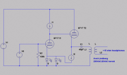
It took a bit of operating point tuning to eliminate some 2nd order harmonic distortion cancellation between stages that obscured the results. The circuit under test is below. I can't stress enough it's a very atypical one with specific consequences and limitations for extrapolating the results to follow. The first tube's cathode load is effectively driven by two CCSs, the only dynamic current being that delivered to the output grid by the gain stage. Since the first tube's static Ip is ~ 1.3 ma, the second's 50ma and the grid load seen by the driver a CF, the change in cathode current due to program is infitesimal. In other words, don't try to extrapolate the results to cover a 12b4 with a 6k plate load.
Attachments
The above circuit was measured four times: as shown, with 1500uF across the cathode LEDs (2 greens), with a 43 ohm resistor in place of the cathode LEDs and with the resistor bypassed. The spectra are shown below.
The output level is 4 volt p-p and didn't change for any condition. Vgk as shown. The load was a pair of AKG 701 both sides paralleled, so ~30 ohms by the spec sheet. At this level the tones were clearly audible over a thousand square feet, I would estimate 108 dB average at the ear.
As the graphs show, both bias techniques were essentially equivalent. The sand-phobic have a second option if circuit permits. Don't worry too much about the 3rd digit, pausing the measurement software caused it to fluctuate more than the circuit changes. If there was one consistent result it came from bypassing the resistor. Distortion might have increased ~10%. Otherwise the bypass tests suggest neither techique has a significant impact on distortion spectra to well below the floor of any available music source. 1500uF @ 2 kHz is under 0.1 'ohm' AC impedance.
Once the final op point of this circuit are sorted and it's time to build, I'll probably return the four combined stages of both channels through a single 22 ohm resistor. I'm impressed with the results and now see why it sounded so good (in this circuit!.)
An externally hosted image should be here but it was not working when we last tested it.
The output level is 4 volt p-p and didn't change for any condition. Vgk as shown. The load was a pair of AKG 701 both sides paralleled, so ~30 ohms by the spec sheet. At this level the tones were clearly audible over a thousand square feet, I would estimate 108 dB average at the ear.
As the graphs show, both bias techniques were essentially equivalent. The sand-phobic have a second option if circuit permits. Don't worry too much about the 3rd digit, pausing the measurement software caused it to fluctuate more than the circuit changes. If there was one consistent result it came from bypassing the resistor. Distortion might have increased ~10%. Otherwise the bypass tests suggest neither techique has a significant impact on distortion spectra to well below the floor of any available music source. 1500uF @ 2 kHz is under 0.1 'ohm' AC impedance.
Once the final op point of this circuit are sorted and it's time to build, I'll probably return the four combined stages of both channels through a single 22 ohm resistor. I'm impressed with the results and now see why it sounded so good (in this circuit!.)
- Status
- This old topic is closed. If you want to reopen this topic, contact a moderator using the "Report Post" button.
- Home
- Amplifiers
- Tubes / Valves
- An almost DIY 6DJ8 Linestage