You clearly point to a horribly expensive commercial product in post #12. (Xenotron 3PX8)
Is that not the product that demonstrates your "conclusions" and/or a product you're involved with somehow?
I can see Charlie's point. You've made some claims and referred to a solution...yet it's proprietary and you won't discuss it.")
This posting is not in the appropriate area. It should have been placed (originally) in the Vendor's section of the website where commercial postings are appropriate.
Cheers,
Dave.
Is that not the product that demonstrates your "conclusions" and/or a product you're involved with somehow?
I can see Charlie's point. You've made some claims and referred to a solution...yet it's proprietary and you won't discuss it.
This posting is not in the appropriate area. It should have been placed (originally) in the Vendor's section of the website where commercial postings are appropriate.
Cheers,
Dave.
I looked above and found the reference you all are referring to (not a part of the original post) which was posted after several discussions and a referral to Linkwitz web site was posted. So it's O.K. to link to your favorite product? The link to manufacturer web site was supposed to go to technical info on xover behavior.
You don't like the results of the analysis, can't find a way to legitimately dispute the result, so you resort to character assassination of the author? Now who is being distasteful?
You don't like the results of the analysis, can't find a way to legitimately dispute the result, so you resort to character assassination of the author? Now who is being distasteful?
Given the quality of today's gain stages, I doubt the point about single or minimum gain stages is relevant to much. Since many excellent sounding systems have been built with 4th order Linkwitz-Riley filters, possibly the analysis is concentrating on things that don't need to be optimized to the last 0.1 dB for best sound?
I must admit that i've always read/heard & thought that 4th order Linkwitz-Riley filters were best ! But having said that, the very first 4 way HQ sound system i designed & built for a smallish nightclub years ago, used a combination of 1st & 3rd order Xovers. Active 3rd on the bass & to mids, passive 3rd on the HF slot bullit, & 1st on the others including horn. I also ensured that all drivers were phisically time aligned. The sound quality & stereo seperation & depth & detail etc was Outstanding. So something/s must have been right about it. Oh & nothing ever blew up, & that was with no comp/lim & frequent soft clipping !
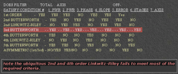
On Auratron - Components and Systems 3PX8 ELECTRONIC CROSSOVER DESIGN PHILOSOPHY there is an interesting table which summarizes the characteristics of various Xover configurations. The visual formatting of the chart needs changing though
Until JrmEng posted recently, i hadn't seen his www & info etc before. So thanks for posting
I understand some of the others points about self promotion etc, but as long as it's informative etc, i don't mind !
Attachments
SPICE is useless for analyzing distortion in op-amp gain stages. The analysis is only able to focus on amplitude/phase aspects. More stages (in series) = more HF distortion. User has to decide what to compromise.
There's no question that more of anything in series will give you more of whatever shortfalls it might have. Still, I think we've moved beyond the point where using a few gain stages would be considered anything other than a minor theoretical issue. Were that not true, all recorded music would be unlistenable.
As to the uselessness of Spice, that's like saying math is useless. What kind of HF distortion are you referring to? I'm a big believer in bench measurements and a bit skeptical of Spice results until proven correct, but once there's agreement between the two, you can forge ahead with great confidence using Spice.
I understand some of the others points about self promotion etc, but as long as it's informative etc, i don't mind !
The analysis page is now self-contained and does not need an external link that might be misconstrued as "self promotion". See "Conclusions".
The SPICE models for opamps are useless for predicting distortion. They use only 2-4 parameter modeling (i.e. near ideal) for the internal transistors/diodes.
SPICE is extremely accurate for frequency response/phase of complex circuits.
OK, let's take a step back for a minute to try and see the bigger picture here with respect to loudspeaker crossovers.
If you want to be accurate, you will need a more accurate model of the driver(s). So far (I believe) you have modeled drivers as second order HP stages. This is a first approximation, however, drivers have a bandpass character meaning that you need to add to that a LP filter (typically 4th order) to approximate the upper end behavior. Herein lies the problem with approaching this from the electronics side: every driver model has different HP and LP behavior, and this would still only be an approximation of a real driver because it does not include cone breakup, effects from mounting the driver in a cabinet (e.g. baffle step type effects) and so on. So what you have is electrical modeling of the crossover filters, so you are missing some rather important aspects of the real world system. A loudspeaker system includes other important issues that relate to the quality of sound reproduction such as the finite excursion capability of the drivers, their frequency dependent distortion characteristics, interference between the soundwaves propagating outward from each driver depending on the relative phase angle at any observation point in space, the position in three dimensions of the acoustic center of each driver, etc., etc.,etc.
Essentially, modeling like you are doing with SPICE can only take you so far and to design a loudspeaker (the reason for the crossover in the first place) you need to start taking measurements on an actual system FIRST and then subsequently design a crossover system based on the measurements. The fact is that once you throw in all the driver and system related issues the conclusions obtained from crossover only modeling are no longer all that valid, really. As an example, the main premise of the SPICE studies is to examine how the crossover filters sum together. That is all well and good, but without the acoustical side (the drivers) you are skipping over some rather important points about a loudspeaker. You MUST know driver phase (including propagation delays, etc not just HP LP modeling) to begin to say anything meaningful about a loudspeaker crossover and how things sum together, which is I believe what you are trying to model. Some important aspects of filters, like group delay, don't seem to be known to you.
This is exactly the problem that I had, and still have, with the approach taken by Douglas Self in his recent book "Active Crossovers for Loudspeakers". He is an excellent designer of electronics, including crossover electronics, however, in his book he steps through an active design without any good model of the loudspeaker driver (e.g. the frequency dependent phase behavior) as if assuming that phase of a driver is 0 degrees for all frequencies. Not even a novice loudspeaker designer would make this kind of mistake. All of his electronics designs are excellent but his loudspeaker crossover design approach as described in his book is suspect. He doesn't even mention anything about driver phase, so I have to assume that he doesn't know much about the subject and how important it is to know that accurately in order for the driver responses to sum together in the desired way.
I see some of the same type of mistakes in your work, JrmEng. Your SPICE modeling is fine, but you are pursuing electrical models to the nth degree without taking into account some other rather important aspects of loudspeakers. This is the source of my chagrin, not an attempt at character assassination as you have mentioned. Again, since you are designing a loudspeaker crossover and not just a filter network for electrical purposes, your simulations only apply to a small portion of the crossover design problem. Another example of this is worrying about amplifier distortion, which is on the order of 10-100 times smaller than driver distortion, or less. Measure the distortion in the acoustic output of enough drivers (home audio types) and you will see that driver distortion just isn't very low, especially as SPL level increases above 90dB@1m, which is not super loud by any means. Driver distortion nearing 1% THD is not uncommon! As an example, Doug Self mentions that he laughs any time someone objects to using a 5532 op amp, because he knows that the signal passes through hundreds of them on its way through the recording chain. That's right, hundreds of op amps! Is one or two more going to make that much difference (if designed and implemented correctly)??? This is a device that has less than 0.001% distortion, around one hundred to one thousand times less than a driver.
What I am getting at here is that you might want to take a step back and put your modeling into perspective with respect to the overall task of designing a loudspeaker crossover network. What you have done is certainly valid for the electrical filters, and you have started to add in some characteristics of the driver to your models. But you are still a long way from the complete picture, which unfortunately doesn't lend itself to general modeling because it is driver and system dependent to a large degree. I've done this as a hobby for a long time, and I have written some free tools for designing a crossover system based on driver measurements. These are coming from the other direction compared to your efforts, that is they assume ideal, lossless and distortion free filters in the crossover network. Loudspeaker system design involved both electrical and acoustic modeling, so we both have something to add to the mix. I'd be happy to share my modeling experiences with you, as long as it is used for DIY purposes. For commercial purposes please contact me to work something out.
-Charlie
Well and good, but the original post is not intended to analyze the complete xover-driver interaction, only to demonstrate the characteristics of various xover implementations as a starting point and expose many common misconceptions.
One of the first programs I wrote solved the complete mechanical equivalent circuit for a loudspeaker in a vented/sealed box with damping, mutual coupling, Bl effect, etc.
I also developed software to directly control the MLSSA, originally TransView, data acquisition board (www.mlssa.com) with features such as implementing automation of T/S paramaeter measurements and easy determination of time-alignment.
Last edited:
Let me be blunt then, many of your "conclusions" are at best suspect and at worst wrong because you don't include key details about the drivers or loudspeaker system in your models. Obviously you can't do that because you are only doing SPICE modeling.
You can not take observations from your electrical modeling of filters and apply them to a loudspeaker where things will be very different because there is an entire acoustic side that you do not account for. You say things like "The sum of the total power radiated by each driver (must be considered)" but you have a completely useless or missing model of the driver radiation!
You seem to assume that the filter output that is directed to this driver describes what the driver is doing in the acoustic domain in terms of power, phase response, etc, etc. Nothing could be further from the truth.
That's about all I care to say in this thread.
Let me be blunt then, many of your "conclusions" are at best suspect and at worst wrong because you don't include key details
Give the guy a break. There's nothing wrong with his data. Of course there could be more details but that's pretty standard and it dosnt mean the conclusions are wrong. And it sure beats the typical post here that say "blah blah x-over is the best because it sounds that way". The data is there if you don't want use it don't. But don't go on and on slagging the poster.
Thank you jreng for the information. A lot of appreciate it.
A logical approach to choosing an xover.
You could not be more wrong and you are trying to over complicate the issue.
The heart of any quality sound system is the (electronic) crossover. A logical approach would be to choose the steepest-slope xover up to the point where negative side-effects become objectionable, then choose drivers for the respective frequency ranges that operate linearly over the required bandwidth. This is not dificult given the quality of today's drivers.
Why aggravate yourself by trying to correct flaws in ill-conceived drivers by screwing up an otherwise optimum xover?
Haven't you realized yet that, more often than not, the cure is worse than the curse?
Essentially, modeling like you are doing with SPICE can only take you so far and to design a loudspeaker (the reason for the crossover in the first place) you need to start taking measurements on an actual system FIRST and then subsequently design a crossover system based on the measurements.
-Charlie
And we started "measuring" 40+ years ago and haven't stopped since.
All of the conclusions we have postulated are based on that experience.
Computer modeling for speaker drivers can be very accurate for low frequencies in the linear range below where ka=1. Beyond ka=1, modeling begins to fail due to too many random interactions. When attempting to operate a driver above where ka=1 (not recommended), it is best to rely on measured response, and choose a driver that is acceptable. While low frequency magnitude/phase behavior can be easily accounted for, high-frequency anomolies cannot be corrected in a way that yields a pleasing sound.
There's no question that more of anything in series will give you more of whatever shortfalls it might have. Still, I think we've moved beyond the point where using a few gain stages would be considered anything other than a minor theoretical issue. Were that not true, all recorded music would be unlistenable.
The crossover I use has 3 stages/channel for the tweeter section - An LP ultrasonic filter, the HP, and a gain buffer, for a total of 6 stages in stereo. Replacing these 6 opamps with anything other than OPA627 results in a significant decrease in tweeter - mid-range clarity (LP is cascaded into the mid-range and subsequent lower sections.). Your assumption is contradicted by experimental results.
- Status
- This old topic is closed. If you want to reopen this topic, contact a moderator using the "Report Post" button.
- Home
- Source & Line
- Analog Line Level
- Amplitude Errors in the Summed Response of Audio Crossover Filters