Here ya go: Link5th element said:A quick browse at Farnell seems to show they don't stock thermal grease.
Are we saying it's resolved then for now, as far as can be.
P1 altering the bias, that looks to be down to the circuit design, Why this obsesion with "visual symmetry" in modern designs anyway.
Complementary transistors are anything but. !!!! Better stop ranting")
It would be interesting to refit the protection and repeat the resistive test again. And just me being picky, what wattage is R34, the 10 ohm in the Zobel network.
P1 altering the bias, that looks to be down to the circuit design, Why this obsesion with "visual symmetry" in modern designs anyway.
Complementary transistors are anything but. !!!! Better stop ranting
It would be interesting to refit the protection and repeat the resistive test again. And just me being picky, what wattage is R34, the 10 ohm in the Zobel network.
BTW, those sil pad specs are 0.3 degC/W for a square inch - you need to adjust for your actual contact area. I think it would be fairer to rate pads for each type of device, still, the figures wouldn't look so good then ...
Maybe you could try mica washers - if you have some spares try splitting then to make then even thinner !!!!
Maybe the actual figure is closer to 1.something degC/W - which is more consistant with your 30C across the case // heatsink junction @ 30W.
Maybe you could try mica washers - if you have some spares try splitting then to make then even thinner !!!!
Maybe the actual figure is closer to 1.something degC/W - which is more consistant with your 30C across the case // heatsink junction @ 30W.
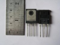
Yeah, that mica kit should work. Be sure they aren't too thick- read the Elliot page about that. You'll notice that most silicone and glass pad makers never compare their products with mica and grease, and they often switch thermal units to make direct comparisons with other vendors more difficult. If they were much better than mica and grease, they'd be shouting it from the rooftops, with numbers to prove it. Farnell simply published the lowest number they could find, though it's far from the number you'd get in actual practice with a specific package type. It's accurate, but completely misleading. BTW, I don't have good data on the package you're using- can you post a small photo of the back side with some dimensions? I assume it has exposed metal, and isn't a fully insulated package. Most of the heat transfer will be from the metal area, not the surrounding plastic, though it obviously contributes something.
Mooly said:Are we saying it's resolved then for now, as far as can be.
P1 altering the bias, that looks to be down to the circuit design, Why this obsesion with "visual symmetry" in modern designs anyway.
Complementary transistors are anything but. !!!! Better stop ranting
It would be interesting to refit the protection and repeat the resistive test again. And just me being picky, what wattage is R34, the 10 ohm in the Zobel network.
R10 be three watt.
I'd be interested in that test too, however I would prefer to do it once I've sorted the mica/grease thingy. It may turn out that improved heat conduction does a lot more then just giving me dirty fingers.
BTW, I don't have good data on the package you're using- can you post a small photo of the back side with some dimensions?
Attachments
Mooly said:R10 , R34
Whichever, 3 watts is OK (just), if you test at full power at above 20Khz it might protest.
>.< R34 = 10 ohms = R10.

Yes R34 = 3 watt.
help please:
i have ampli project that was 10 year still doesn't finish
that is the picture:
can anyone tell me what's the type?
thx
i have ampli project that was 10 year still doesn't finish
that is the picture:
An externally hosted image should be here but it was not working when we last tested it.
can anyone tell me what's the type?
thx
OK, now I know exactly what package you've got. The metal area (where most of the heat transfer takes place) is 0.3 square inches. As DRC said above, you're certainly getting 1.something degrees C per Watt. Throwing in the thermal resistance of the package-to-junction, and a warm heat sink, the junction temperature is likely going sky high. Very curious to know what happens with the mica! BTW, the grease used is surprisingly unimportant if the parts are flat and the layer thickness is very small. For that last little bit of performance I've used the Arctic Silver products and they're first rate, though my usual goo is Dow 340. You can also buy thermal grease in some auto parts stores, as it's needed for servicing the electrical systems in newer cars.
Amplifiers I used to build about 20 years had the same type of output current limiting circuitry. If my memory serves me correctly, try increasing R21 and R27. Try for example, 2.2 k, then possibly 4.7k and see how the limiting circuitry behaves. Unfortunately I don't know how to calculate the correct values, but I am sure someone here could.
Hope this helps
Hope this helps
5th element said:
So far we've managed...
1) To eliminate the DC offset issue by altering the input filter.
2) Show the amplifier can produce 140 watts into just over an 8 ohm load before clipping.
3) Probably rule out oscillation, from the amp passing the AM radio test.
What still irks me.
1) The bias is very dependant on the value of P1 (R13), this shouldn't be the case.
2) Why was the output protection circuitry tripping prematurely.
All in all, from my point of view, things don't seem too bad and with the equipment I've got at my disposal, I am rather happy to leave this where it is.
I would just like to thank everyone who has offered advice, allowing me to sort out some of the problems I had with these, and perhaps the problems the amplifiers had weren't quite so severe, more the load I'm trying to drive is rather difficult.
pinyoro said:Amplifiers I used to build about 20 years had the same type of output current limiting circuitry. If my memory serves me correctly, try increasing R21 and R27. Try for example, 2.2 k, then possibly 4.7k and see how the limiting circuitry behaves. Unfortunately I don't know how to calculate the correct values, but I am sure someone here could.
Hope this helps
Thanks for the response I will give that a go and see what happens.
I have now replaced the Sil-pads with Mica and thermal grease. Directly comparing one channel with another the FETs are quite a bit cooler, which is always a good sign. I am yet to do any testing as I am too tired at the moment, but I will report back when things pick up.
P.S. Doing this reminded me of why I hate using thermal grease.
I'd change that protection circuit to just using 10V zeners with 1n4148 or equivalent in series, connected before gate resistors. The self protection offered by laterals is insane. I couldn't blow one up (hitachi in plastic package) with 50V and 10A available on a way too small heatsink even when trying! I used 9V drive to the gate through a 330 ohm or so resistor. Current limited drive to the gates is a must though as some internal thyristor structure is what protects the transistor from overtemperature.
Have a look here for more information:
http://www.diyaudio.com/forums/showthread.php?s=&threadid=111116
Have a look here for more information:
http://www.diyaudio.com/forums/showthread.php?s=&threadid=111116
Thread Resurrection!
My fathers work had a clear out on some old electronics gear they weren't using and he managed to nab a scope for me. As a result of this I purchased some power resistors to give the amps a proper test, where I got some encouraging and some rather odd results.
The power resistors came in standard values so all I could get were 4.7 ohm, not quite 4 and 8 ohm loads, but close enough.
First I tested the amps without any protection circuitry where they delivered.
~156 watts into 9.4 ohms.
~220 watts into 4.7ohms.
I then connected up the protection circuitry and was pleased to find that into a purely resistive load, the results were exactly the same.
~156 watts into 9.4 ohms.
~220 watts into 4.7ohms.
I then tried driving 2.35 ohms and got again 220 watts.
This looked perfectly normal, so I altered the protection circuitry to limit at much lower levels, just to check it was working. When tested like this, the protection circuitry would clip the peaks of the waveforms, as expected. Encouraged by this I tried hooking up the loudspeakers, where once again where I was confronted with the ugly sawing noise. Only this time I could actually see what was happening, rather then guessing.
And here are the results.
The first picture is how the waveform looks as soon as the sound starts, the second picture is what happens if you turn it up a bit more.
The scope is working at 20 volts per division.
Needless to say this is not what I was expecting and I currently have no idea what this is Some form of crossover distortion would be my uneducated guess, but it doesn't look anything like the examples I've seen.
Anyone any ideas?
Thanks in advance,
Matt.
My fathers work had a clear out on some old electronics gear they weren't using and he managed to nab a scope for me. As a result of this I purchased some power resistors to give the amps a proper test, where I got some encouraging and some rather odd results.
The power resistors came in standard values so all I could get were 4.7 ohm, not quite 4 and 8 ohm loads, but close enough.
First I tested the amps without any protection circuitry where they delivered.
~156 watts into 9.4 ohms.
~220 watts into 4.7ohms.
I then connected up the protection circuitry and was pleased to find that into a purely resistive load, the results were exactly the same.
~156 watts into 9.4 ohms.
~220 watts into 4.7ohms.
I then tried driving 2.35 ohms and got again 220 watts.
This looked perfectly normal, so I altered the protection circuitry to limit at much lower levels, just to check it was working. When tested like this, the protection circuitry would clip the peaks of the waveforms, as expected. Encouraged by this I tried hooking up the loudspeakers, where once again where I was confronted with the ugly sawing noise. Only this time I could actually see what was happening, rather then guessing.
And here are the results.
The first picture is how the waveform looks as soon as the sound starts, the second picture is what happens if you turn it up a bit more.
An externally hosted image should be here but it was not working when we last tested it.
An externally hosted image should be here but it was not working when we last tested it.
The scope is working at 20 volts per division.
Needless to say this is not what I was expecting and I currently have no idea what this is
Some form of crossover distortion would be my uneducated guess, but it doesn't look anything like the examples I've seen. Anyone any ideas?
Thanks in advance,
Matt.
I don't know what the step in the wave is.
The spike (60Vpk) and that around it looks like it might be the output stage shutting off and back emf from the speaker.
Could the trigger level of the protection be set too low for a reactive load?
220W into 4r7 is ~45.5Vpk and ~9.68Apk.
What is the peak current into the reactive speaker? Could it be higher than 9.7Apk?
The 220W into 2r35 seems to indicate that the amp is refusing to meet current demand.
It looks like the VI limiter is doing it's job and there is too little current available at low output voltages. This will cause pretty weird behaviour and ugly noises.
In the schematic (http://www.turboimagehost.com/p/325123/amp.GIF.html) only 4A total is allowed around zero crossing which is a bit low - you'd want it to be at least half the peak output current into the DCR of the speaker. 4A around zero crossing is only good for about 24V peak output: 70W for a 4 ohm speaker.
What is the impedance of the speakers connected in the picture? Signal frequency?
I wouldn't use that kind of protection circuit with lateral fets though - gate zeners set for an appropriate peak current goes a long way protecting this kind of FET and won't cause those kinds of ugly spikes. To protect from sustained overload approporiate fuses (in series with each drain connection is a good place) or input signal mute/speaker relay disconnect controlled by some kind of an impedance detector can be used.
I tried to deliberately destroy some Hitachi lateral MOSFETs (2SK135,2SJ50) but even with 50V Vds and 10V Vgs - dissipating 200W at 90 deg C heatsink they wouldn't give up. This is double the rated 25 deg C dissipation at 90 degrees! IIRC I did this to them for over a minute without failure. Sure, it's not good for them but in an amplifer a fuse would blow within a second or so and a relay/mute could be made to react even faster so with that kind of protection a continuous short on the output would still be safe. The speaker relay is actually even used in many BJT amps for short protection!
AndrewT said:I don't know what the step in the wave is.
The step is how the waveform looks just as the sawing starts, without any spikes or "roughness". The spikes and the jagged behaviour only start if I push the amp further.
The spike (60Vpk) and that around it looks like it might be the output stage shutting off and back emf from the speaker.
Could the trigger level of the protection be set too low for a reactive load? [/B]
I doubt it. The resistor setting the trigger level is at 100 ohms, I had to lower it to around 20 ohms to actually get it to falsely activate into the 4.7 ohm dummy load. Slone does say you can increase its value to 150-200 ohms if it is triggered too early, but I have done this and it does very little.
220W into 4r7 is ~45.5Vpk and ~9.68Apk.
What is the peak current into the reactive speaker? Could it be higher than 9.7Apk?[/B]
I don't think I have the equipment to measure this.
The 220W into 2r35 seems to indicate that the amp is refusing to meet current demand. [/B]
Well it only has two pairs of output FETS I don't think its capable of much more.
- Status
- This old topic is closed. If you want to reopen this topic, contact a moderator using the "Report Post" button.
- Home
- Amplifiers
- Solid State
- Amplifier Troubleshooting.