MarcelvdG
I think it is impossible to add current mirrors as collector impedance in a symmetrical amplifier because you need a determined DC voltage in order to bias the VAS. In the single ended version you bias the VAS with a current generator and then adjust the DC-offset with the diffstage.
I think it is impossible to add current mirrors as collector impedance in a symmetrical amplifier because you need a determined DC voltage in order to bias the VAS. In the single ended version you bias the VAS with a current generator and then adjust the DC-offset with the diffstage.
We just discussed this problem in the thread about the amp from Randy Slone's book. When you combine a symmetrical input stage with current mirrors, the voltage at the LTP collectors is pretty much undefined. This means the current in each VAS depends on parasitics like beta, and hence you have the situation where the two halves of the circuit start fighting each other. There did not seem to be any feasible way out of this.
Regards,
Eric
Regards,
Eric
janneman said:
Andy,
If I have followed this correctly, you confirm that with the equalised loop gain stuff, the symmetrical version produces more 3rd order THD in absolute terms, compared to the assymmetrical version? Amazing!
Jan Didden
Yes, that seems to be the case. The data of my original post on this has the numbers. I was surprised by this result too. It seems intuitively reasonable that a complementary design reduces the even harmonics, but not at all obvious that the 3rd harmonic should be at all higher. I'm unconvinced that this is some kind of necessary condition though.
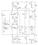
I’m not sure all this simulation really sheds any light on “subjective effects” but I do have a way to bias the balanced circuit:
I1 is the 1 mA reference current for the VAS bias servo G1, R11 = 0.33 ohms gives 3 mA VAS bias current with G1 = 1 A/V, the servo loop completes as a common mode signal through the input current mirrors and ideally doesn’t couple with the differential gain loop – still not sure what a good practical implementation would look like
Perhaps andy or jan can use this approach to make an apples vs apples distortion comparison
I find that lots of loop gain helps if you want to minimize distortion, as can be seen from the distortion simulated with the 2 pole compensation shown (which isn’t actually helping much @ 2KHz due to the low VAS gain),
2nd harmonic 2KHz –93 dB, 3rd –105 dB;
gain of 40K @2KHz is limited by VAS loading the diff input mirrors, gain increases as VAS bias is decreased
20 KHz –102 dB 2nd , -117 3rd; with 39K gain (this much loop gain wouldn’t be available at this frequency without the 2 pole compensation)
I suspect the numbers would look a lot better with the Baxendall “Super Pair” composite VAS I show in the “Class A headphone amplifier” thread (where the 2KHz gain exceeds 3 million!) but I’ve reached my Q limit in orcad demo (is LT switcher cad better than it was a few years ago? does anyone have experience with AIM Spice demo? Or other free/cheap Spice suggestions)
Attachments
"I1 is the 1 mA reference current for the VAS bias servo G1, R11 = 0.33 ohms gives 3 mA VAS bias current with G1 = 1 A/V, the servo loop completes as a common mode signal through the input current mirrors and ideally doesn’t couple with the differential gain loop – still not sure what a good practical implementation would look like"
Just replace R11 with a floating current source - no servos required")
Lukas
Just replace R11 with a floating current source - no servos required
Lukas
andy_c
I was the one that stated that symmetric designs introduce third harmonics from the beginning of this thread.
The reason for my statement is an article from The Audio Amateur that I have a copy of and it is written by Erno Borbely. The article describes nonlinear distorsions, the cause for them and also how to measure them.
In a simple curve plot it all became obvious to me. If you let a gainstage with a square transfer function amplify a signal, you introduce second harmonic distorsion. If you combine a N-channel and P-channel device you end up with a transfer function consisting of both a square and a cubic part allthough the square part is smaller than with a SE-stage. The cubic part will introduce a third harmonic.
It is very simple to see it with your own eyes. Just draw the transfer function of a push pull stage or a differential stage (they act the same) and see how it reminds you of a x3-curve (cubic).
This thread has been wonderful, very "food for thought" like. No war, no really sure statements, wonderful. 
I will fool around more with SwitcherCAD after the vacation. I'm not totally convinced but I have an open mind. Don't trust the simulation too much though.
As a conclusion we can all agree on that if the amp is well designed there are not any huge differencies in distortion.
I will fool around more with SwitcherCAD after the vacation. I'm not totally convinced but I have an open mind. Don't trust the simulation too much though.
As a conclusion we can all agree on that if the amp is well designed there are not any huge differencies in distortion.
peranders
You are absolutely right. It has been very interesting. I am very impressed by the competence present at this forum.
Would be interseting if Nelson Pass or Douglas Self commented this issue. They may allready be fully aware of the matter. Maybe that is why Self do not bother with symmetrical designs?
p00ge
For some reason I don't thin that is why Self doesn't go complimentary. I beleive he wants a current mirror for balancing the LTP. Leach, on the other hand, states on his web site:
"If only a single diff amp is used, the only way to obtain a complementary second stage is to take differential outputs from the diff amp and to use a current mirror to drive the other side of the second stage. Frequency compensation of these circuits is tricky because the two signals from the outputs of the diff amp to the output of the second stage travel through paths with different amplifier configurations. Matching the gain and phase characteristics of these paths is difficult. For good stability, you usually end up with a lower open loop bandwidth and slew rate than you could obtain with complementary diff amps at the input.
In addition, I don't like to use a current mirror in a gain path. With discrete transistors, it is difficult to match the two transistors in the mirror. Even when they are well matched, the Early effect and temperature effects cause output current to be greater than the input current. Indeed, the current ratio varies with voltage across the second transistor, which varies with the signal. Series emitter resistors in the mirror are a partial fix for this problem."
Yes Peranders, this has been a great discussion and really got a lot of clever people thinking - wonderful stuff!
Andy_c's simulation has proved a point that we are all perhaps overlooking, and that is that it is not possible to compare symmetrical to asymmetrical stages in isolation - whichever you choose determines the configuration of the rest of the amp, and the fine details of implementation make equal comparisons impossible.
We can make generalisations about which topology is superior for whatever technical reasons we personally consider to be most important. But at the end of the day good amplfiers can be made with either configuration.
Having built both Self's "blameless" class B amp and his "precision preamplifier" and found both to completely destroy my enjoyment of music, I certainly don't think that concentrating on distortion figures alone is the way to produce a good amplifier - after all, the amplifier's purpose is to allow us to enjoy music, we don't connect it to a distortion analyser and watch the low figures for musical satisfaction...
So, back to my original question: how about the subjective effects of asymmetrical vs symmetrical (generalised opinions are perfectly acceptable)?
Blameless Blame ?
Eric.
Are you saying that these are too clean and therefore characterless and this destroys your enjoyment ? - or what ?.Having built both Self's "blameless" class B amp and his "precision preamplifier" and found both to completely destroy my enjoyment of music, I certainly don't think that concentrating on distortion figures alone is the way to produce a good amplifier -
Eric.
AKSA said:
we now need to calm the savage breast ...
Hugh
I would be very interested in partaking to that effort.
Kidding aside, I am learning a lot from this discussion.
Effects of cascoding of the VAS
Well, I promised myself I wouldn't mess with this simulation any more. However, the designs I've been playing with lately have all used cascoding of the VAS in some form. So I just wanted to evaluate the effects of VAS cascoding on the simulated distortion. After seeing the results, I suddenly remembered something a math teacher I had in college used to say:
"You're not going to like this".
I cascoded both VAS transistors in the complementary amp of course. I used small-signal transistors for the CE amps because of the low voltage across them, and used the MJE340/350 for the common base portion. Also, I measured the loop gain at 20 kHz in the new configuration. For the complementary design, it was 1 dB higher than without cascoding. I believe this was because the collector-base capacitance of the VAS transistor no longer appears in parallel with the compensation cap, making the gain-bandwidth product a little higher. So I increased the compensation cap to make the 20 kHz loop gain the same as before. Now the common base amp is biased with its base at 5.6 Volts away from the rail instead of 1.6 Volts. So I increased each supply voltage by 4 Volts to keep the clipping level the same.
I did a similar thing with the single-ended configuration. In addition to cascoding the VAS gain stage, I cascoded the constant current load as well, using the low-power transistors of the CE configuration in the same way as with the complementary stage.
The complementary design is shown below.
Attachments
andy_c said:Also, I measured the loop gain at 20 kHz in the new configuration. For the complementary design, it was 1 dB higher than without cascoding. I believe this was because the collector-base capacitance of the VAS transistor no longer appears in parallel with the compensation cap, making the gain-bandwidth product a little higher. So I increased the compensation cap to make the 20 kHz loop gain the same as before. Now the common base amp is biased with its base at 5.6 Volts away from the rail instead of 1.6 Volts. So I increased each supply voltage by 4 Volts to keep the clipping level the same.
Would you increase the compensation cap in real life too if the amp is stable?
Or would you accept the higher gain and improved frequency and phase responses of the cascode?
The distortion of the complementary amp with cascoding is much lower now. All harmonics above the third are below the residual of the FFT for the complementary design. I'll have to play around with the FFT parameters to improve this. But that's for later. The results were:
Complementary:
2nd harmonic = 83.2 dBc
3rd harmonic = 77.5 dBc
The third harmonic has improved by about 15.5 dB over the complementary design without cascoding. That's a significant improvement.
Then I ran the single-ended version. I had to increase the compensation cap slightly to get the same gain-bandwidth product, similar to what I did with the complementary design. The results were:
Single-ended
2nd harmonic = below residual of 90 dBc
3rd harmonic ~= 93 dB (residual is about 95 dB)
So not only is the third harmonic about 15 dB better for the single-ended design than the complementary design, but the surprising result is that the second harmonic is better too.
I'm at a loss to explain this. I'm running out of time, so I'll just post the schematic of the single-ended design and comment more later.
Attachments
grataku said:
Would you increase the compensation cap in real life too if the amp is stable?
Or would you accept the higher gain and improved frequency and phase responses of the cascode?
I'm trying to keep the gain-bandwidth product exactly the same as before cascoding, only for the purpose of evaluating the change in distortion due to the improvement in the linearity of the open-loop amplifier. I don't want any change in loop gain clouding the issue of where the improvement came from (more feedback or improved linearity).
If I were designing this as an amp for my own use, I'd make the gain-bandwidth product much smaller in order to maintain stability into difficult loads. But that's another story entirely.
Pabo said:andy_c
I was the one that stated that symmetric designs introduce third harmonics from the beginning of this thread.
The reason for my statement is an article from The Audio Amateur that I have a copy of and it is written by Erno Borbely. The article describes nonlinear distorsions, the cause for them and also how to measure them.
In a simple curve plot it all became obvious to me. If you let a gainstage with a square transfer function amplify a signal, you introduce second harmonic distorsion. If you combine a N-channel and P-channel device you end up with a transfer function consisting of both a square and a cubic part allthough the square part is smaller than with a SE-stage. The cubic part will introduce a third harmonic.
It is very simple to see it with your own eyes. Just draw the transfer function of a push pull stage or a differential stage (they act the same) and see how it reminds you of a x3-curve (cubic).
Pabo,
I think the issue is not the 3rd harmonic as such, everybody accepts the way it is generated as you stated. The issue was that there was a difference in 3rd harmonic level between symmetric and assymitric amps. We already know that because of the symmetry, we would expect less 2nd harmonic which would make the 3rd stand out more. But know it APPEARS that symmetric amps generate a higher absolute level of 3rd harmonic. I'm still sceptic, but so far I only have my gut feeling to back it up.
Jan Didden
Question to ANDY_C
Andy,
I've been staring at your diagrams, just an idea. There is quite a lot of local feedback in the LTP (300 Ohm Re) and the Vas cascodes. I wonder if we are really comparing the virtues of symmetrical vs assymetrical, or that we are looking more at the individual stages. Not sure I am clear, but what happens if we make the Re's of the LTP's in both cases say 10 Ohms only? BTW, at which freq. did you measure those harmonics?
Other thing, if I calculate roughly the influence of the comp caps, assuming a 20x CLG, the 50pF comes to about 1k impedance around 15kHz, no? In parallel with the Rc in the assym case lowers the open loop gain there with 6dB wrt the symm case, because in the symm case the 1k in // with the CS load would still come out around 1k, no? So, I'm not sure how you tweaked the OLG to be the same, but I feel there is a 6dB diff between the two.
Jan Didden
- Status
- This old topic is closed. If you want to reopen this topic, contact a moderator using the "Report Post" button.
- Home
- Amplifiers
- Solid State
- Amplifier topology subjective effects