A computer amplified set of speakers might work for the amp. I have even made a guitar amp for a kid from them by taking one output and feeding it back in to the other through a small cap and pot and presto you have now a mono amp with plenty of gain. You could use any amp that has the ability to take a mic input or phono. aux input would probably not have enough ummph to get though. The idea of testing two identical units is that if you probe the same spot on each board it should be the same therefore zero volt difference. But in the case of yours, probably wont do any good since you might be looking for a cap charging up and discharging, other than an electrolytic cap, and not for a discrete component like transistor. If you connect to the (- out) and ground on channel one you should hear the crackle. Thats the minus side of your amp from the main board to the output amp. Look where the output plugs in to the main board. If you are doubt which side it really is, pos or neg just do the same for each side. next check pin 7 of RN101, this is where the signal is after the input balanced stage and before the circuit you just checked at (-out). If you hear it at (-out) and not at (pin 7 of RN101) then its not the balanced input causing it. Elimination. check at TP2 for the noise. And check at pin 7 of RN102 also. This is all based on if the negative side is the problem.
yeah.yourownfree said:
The idea of testing two identical units
is that if you probe the same spot on each board
it should be the same
therefore zero volt difference
.
this is one way, if you have one working and
one not working amplifier
-- like in a stereo pair
100% identical will not be
but close
because not even one trimmed highest hi-fi stereo pair
will ever be totally identical
in testpoints measurements or output performance!

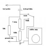
if you use a signal sniffer amp, make sure you include a 0.01uf/100v (or higher voltage) cap between the test probe and the sniffer. remember some of the points in a DC coupled amp are within 0.7V of the rails. also since everything after the VAS stage is at a much higher level (the usual voltage gain for a 100W amp is 30), you might want to add a 10:1 voltage divider in the input of the sniffer as well. when using a sniffer with a cap on the input, you need to provide a discharge path for the cap, that's what the 50k resistor is for. remember to short the test probe to ground after checking nodes near the rails to keep the cap from causing large spikes when you test one point and move it somewhere else (remember you have a charged cap in line with the probe). in the drawing below, the switch is for switching between direct and -10db attenuation. with normal signal levels being line level and higher, an amplified computer speaker will work here. it's best if it's battery powered, but a wall wart powered one will also work.
Attachments
nice Uncle Jed, well said, like the circuit. Lineup, do you have to be so precise? Ok I admit my failure, I'm not perfect. But it was a good thought and theory. I like all comments they are very helpful. I like this site better than some others I've been to. You guys seem great. Hope we can help him solve his problem. Kinda fun doing this. I keep looking to see if he has fixed it yet.
this is great. exactly how i need this stuff explained. i was delighted to wake up this morning and read all the new suggestions, but sadly i couldn't spend all day working on it. i just got back from helping my dad lay carpet would you believe.. what a nice way to spend a sunday
ok so i don't have the components to make the sniffer circuit right now, but i can start probing with the scope those points mentioned by yourownfree and see if i can see that hairiness and spiking i could see on the output.
thanks a million guys, i'll report back soon.
j.
ok so i don't have the components to make the sniffer circuit right now, but i can start probing with the scope those points mentioned by yourownfree and see if i can see that hairiness and spiking i could see on the output.
thanks a million guys, i'll report back soon.
j.
hmm.. after three hours warming up she's still not cracklin'. Always when you're ready to test that intermittent problem it doesn't show.
ah well, at least while I wait Simple Acoustic Trio's album Habanera sounds great through her!
As soon as that crackle starts I'm probing the points described by yourownfree
j.
ah well, at least while I wait Simple Acoustic Trio's album Habanera sounds great through her!
As soon as that crackle starts I'm probing the points described by yourownfree
j.
Murphy's Law of Troubleshooting, Corollary 9:
the intermittant fault never appears when you have your test equipment ready.
Corollary 10:
the intermittant fault never shows up when the technician is present.
i had a yamaha receiver on the bench friday. the complaint was that the Component Video didn't work the unit had sat there for two days embedded in a stack of equipment running just fine. 2 days, and didn't fail once. i was ready to no-fault it and send it back to the client, but i decided to look at the component video board. it has 6 relays on it, and i thought one of the relays might need to be "current cycled" (a process where a 9v battery is connected across the contacts and the coil is driven with a square wave to run just enough current through the contacts repeatedly to remove the oxide layer on the contacts). so i took the board out and began looking at it. i found a zener diode and dropping resistor had melted their solder, creating an obvious cold solder joint. so i replaced the zener and resistor , put the board back in, tested it and sent it on it's way. in all the time the unit was there it never failed, but the cause for the failure when the client had it was easy to find. the amp was hot enough to cook on when i took it out of the stack, byt the solder joint didn't fail even then.
oscillation?
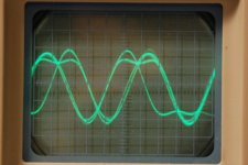
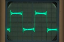
yeah, looks like the crackle is not coming back any time soon.. i've been running it solidly into a big pair of speakers for hours/days. so in the meantime i put a 10KHz square wave in and got this at the output of both channels..
this is not good, is it? is this oscillation? remember the output stage now has MJ21193G/MJ15024G as drivers and MJ21194G as outputs. not sure what i need to do to stabilize.
The schematic is on page 2 of this:
http://www.crownaudio.com/pdf/legacy/psa2schematics.pdf
Attachments
- Status
- This old topic is closed. If you want to reopen this topic, contact a moderator using the "Report Post" button.
- Home
- Amplifiers
- Solid State
- amplifier testing