improvement in PS harmonics and noise
OK, I did a little more playing around and have some new results to show. I think it is related to what Andrew is saying above in some ways.
Andrew: I might already be doing what you say with the MAG. The amp board had an onboard PS originally consisting of a bridge rectifier and two smallish smoothing caps. I removed these. The new outboard PS rails are connected via wires leading to the pcb where the smoothing caps leads were located. I run a single ground wire from the buss bar to the ground on the pcb, and this might be what you are hinting at when you say to "Move the MAG away from the PSU Zero Volts.". The amp pcb has a single ground for both power and line level, not well laid out. This is the reason why I return the speaker grounds directly to the PS - to keep the current out of the amp pcb ground.
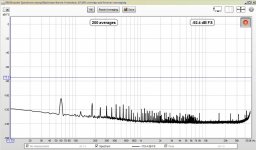
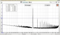
So, I remeasured the system this morning, and the result is shown in attachment 1 "IN MORNING amplifier on but no input signal". The PS noise and harmonics are still present.
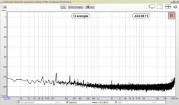
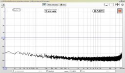
Next I inserted a 1R resistor into the pcb ground wire (connecting the MAG and the zero volt line). This resulted in a significant reduction in the PS noise and harmonics. This is shown in the second attachment, "IN MORNING amplifier on but no input signal - 1R on amp PCB ground". I inserted the resistor at the pcb end of the wire. My thinking was that noise was being induced (the amp is just out in the open) from the PS or nearby equipment. Not sure if that is the case or not, but the result is much improved for sure.
Note that these spectra were taken with the amp on, but not really doing anything (no input). When I drove the amp to full power, it was interesting to see the ripple peak (120 Hz) increase more than 10dB. This probably means I should increase add caps and/or use a transformer with a higher VA rating. The current trafo is only 80VA rated, and the rails drop from about +/-32V to +/-26.5V at the onset of clipping. I measure about 16VAC,RMS at the speaker outputs, which translates to about 32W of power and 22.5VAC,peak voltage. So it looks like the amp can operate up to within about 4V of the rails. If I can keep the rails from sagging, I should be able to get more power out of the amp. I would guess that this is mostly due to the undersized transformer, and I think I have a larger one around I can try (it has a similar secondary voltage).
Am I on the right track here? Any other suggestions?
-Charlie
Locate the Main Audio Ground (MAG) somewhere near all the ground references/connections that the amplifier needs. None on these are on the chassis.
Now run a connection from that MAG to the PSU Zero Volts on that nice big useless buss bar.
Run another connection from MAG to all the exposed metal parts, ready for when you mount it all inside a box.
The buss bars are doing nothing to help your PSU.
If you don't like the statement "useless" then just ignore it.
Move the MAG away from the PSU Zero Volts.
OK, I did a little more playing around and have some new results to show. I think it is related to what Andrew is saying above in some ways.
Andrew: I might already be doing what you say with the MAG. The amp board had an onboard PS originally consisting of a bridge rectifier and two smallish smoothing caps. I removed these. The new outboard PS rails are connected via wires leading to the pcb where the smoothing caps leads were located. I run a single ground wire from the buss bar to the ground on the pcb, and this might be what you are hinting at when you say to "Move the MAG away from the PSU Zero Volts.". The amp pcb has a single ground for both power and line level, not well laid out. This is the reason why I return the speaker grounds directly to the PS - to keep the current out of the amp pcb ground.
So, I remeasured the system this morning, and the result is shown in attachment 1 "IN MORNING amplifier on but no input signal". The PS noise and harmonics are still present.
Next I inserted a 1R resistor into the pcb ground wire (connecting the MAG and the zero volt line). This resulted in a significant reduction in the PS noise and harmonics. This is shown in the second attachment, "IN MORNING amplifier on but no input signal - 1R on amp PCB ground". I inserted the resistor at the pcb end of the wire. My thinking was that noise was being induced (the amp is just out in the open) from the PS or nearby equipment. Not sure if that is the case or not, but the result is much improved for sure.
Note that these spectra were taken with the amp on, but not really doing anything (no input). When I drove the amp to full power, it was interesting to see the ripple peak (120 Hz) increase more than 10dB. This probably means I should increase add caps and/or use a transformer with a higher VA rating. The current trafo is only 80VA rated, and the rails drop from about +/-32V to +/-26.5V at the onset of clipping. I measure about 16VAC,RMS at the speaker outputs, which translates to about 32W of power and 22.5VAC,peak voltage. So it looks like the amp can operate up to within about 4V of the rails. If I can keep the rails from sagging, I should be able to get more power out of the amp. I would guess that this is mostly due to the undersized transformer, and I think I have a larger one around I can try (it has a similar secondary voltage).
Am I on the right track here? Any other suggestions?
-Charlie
Attachments
Last edited:
Do not take any of the Audio Returns (Grounds) to the PSU Zero Volts.
Just the one wire from PSU Zero Volts to Main Audio Ground.
Can you separate the Signal Ground/Return from the Power Ground on the PCB?
This is where you have the option to add that low value resistor.
But remember that the signal attenuation filters and the NFB lower leg must go to the Signal Ground/Return, not to the PCB Power Ground.
Your two pics show on the left the typical 3rd and 5th and other odd harmonics. These are usually the difficult one to get really low. Your right pic shows them much lower. I think this indicates that your resistor is altering the electrical influence rather than a loop radiation influence.
If you could get the 60Hz down then you would be much better.
Last edited:
Qs on where to run speaker return grounds
Hi Andrew,
Thanks for your comments - helpful stuff. I have a couple of questions about what you are calling "Audio Returns (Grounds)" and which I think I am calling the "speaker return grounds". Here goes:
The way I understand how a single ended amplifier works, and I could be completely wrong here, is that the input part of the amplifier scales up the voltage and the output stage of the amplifier pushes or pulls current at that voltage. The output devices on the + rail push current to the load, and the output devices on the - rail pull current from the load. The current from the output devices flows from the rails to the load via the "hot lead" and then returns via the "speaker ground" to the source, which is the power supply. The current does not return to the output stage of the amplifier as I understand it. Since large currents cause small voltages to develop in wires that must have some small resistance (or impedance if you prefer), this is the motivation for keeping power grounds separate from line level grounds. Let me know if I am off on any of this stuff so far...
The amplifier pcb is single sided and I can trace the ground tracks all over. It doesn't look to me like there is a star topology, they just ran the ground traces where it was convenient and there was room to do so. This was not designed to a high standard, it was meant to be a karaoke amp or the like. I doesn't seem possible to cut a trace to form an isolated signal ground. This is why I am running the speaker return (grounds) back to my buss bar - the current flows from the output stage, to the load, and back to the PS ground without flowing through the amplifier pcb itself. I thought that everyone did it this way? If not, why not, e.g. what is the down side? If the speaker returns are connected to the amplifier pcb, won't the current be flowing through the pcb and then out via the ground wire back to the PS ground anyway???
I am basically following the outline given on this page by Rod Elliot:
Power Supply Wiring Guidelines
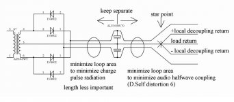
I don't have an earth ground, however; the mains connection is a polarized plug. Note that Rod's Figure 2 (shown below) shows the speaker grounds connected directly to a "buss bar" on the power supply caps.
-Charlie
Do not take any of the Audio Returns (Grounds) to the PSU Zero Volts.
Just the one wire from PSU Zero Volts to Main Audio Ground.
Can you separate the Signal Ground/Return from the Power Ground on the PCB?
This is where you have the option to add that low value resistor.
But remember that the signal attenuation filters and the NFB lower leg must go to the Signal Ground/Return, not to the PCB Power Ground.
Your two pics show on the left the typical 3rd and 5th and other odd harmonics. These are usually the difficult one to get really low. Your right pic shows them much lower. I think this indicates that your resistor is altering the electrical influence rather than a loop radiation influence.
If you could get the 60Hz down then you would be much better.
Hi Andrew,
Thanks for your comments - helpful stuff. I have a couple of questions about what you are calling "Audio Returns (Grounds)" and which I think I am calling the "speaker return grounds". Here goes:
The way I understand how a single ended amplifier works, and I could be completely wrong here, is that the input part of the amplifier scales up the voltage and the output stage of the amplifier pushes or pulls current at that voltage. The output devices on the + rail push current to the load, and the output devices on the - rail pull current from the load. The current from the output devices flows from the rails to the load via the "hot lead" and then returns via the "speaker ground" to the source, which is the power supply. The current does not return to the output stage of the amplifier as I understand it. Since large currents cause small voltages to develop in wires that must have some small resistance (or impedance if you prefer), this is the motivation for keeping power grounds separate from line level grounds. Let me know if I am off on any of this stuff so far...
The amplifier pcb is single sided and I can trace the ground tracks all over. It doesn't look to me like there is a star topology, they just ran the ground traces where it was convenient and there was room to do so. This was not designed to a high standard, it was meant to be a karaoke amp or the like. I doesn't seem possible to cut a trace to form an isolated signal ground. This is why I am running the speaker return (grounds) back to my buss bar - the current flows from the output stage, to the load, and back to the PS ground without flowing through the amplifier pcb itself. I thought that everyone did it this way? If not, why not, e.g. what is the down side? If the speaker returns are connected to the amplifier pcb, won't the current be flowing through the pcb and then out via the ground wire back to the PS ground anyway???
I am basically following the outline given on this page by Rod Elliot:
Power Supply Wiring Guidelines
I don't have an earth ground, however; the mains connection is a polarized plug. Note that Rod's Figure 2 (shown below) shows the speaker grounds connected directly to a "buss bar" on the power supply caps.
-Charlie
Last edited by a moderator:
Locate the Main Audio Ground (MAG) somewhere near all the ground references/connections that the amplifier needs. None on these are on the chassis.
Now run a connection from that MAG to the PSU Zero Volts on that nice big useless buss bar.
Run another connection from MAG to all the exposed metal parts, ready for when you mount it all inside a box.
Andrew,
I think I finally might have a clue about what you are referring to above. See attachment. It's from a very long thread back in 2006 to 2007 (in which you posted often). Someone contributed the schematic. Here is the link to the thread:
http://www.diyaudio.com/forums/solid-state/90728-bob-cordell-interview-power-supplies.html
So is this what you had in mind?
-Charlie
Attachments
Hi Charlie,
Just curious...what software and sound card are you using.
Thanks
Software: REW 5.0, using generator and spectrum analyzer (REW - Room EQ Wizard Home Page)
Soundcard: M-Audio Firewire 410 @ 96kHz
Yet another update... I have been trying to eliminate this "hash" type of distortion that I have been seeing with a chip amp (STK4191V, 50W+50W). There would not be anything visible in the spectrum when the amp was on, but with no input signal - in this case the spectrum was mainly noise. When a single frequency tone was input and the amp was operating at a power level above 10mW the hash would show up.
I scratched my head about what could be causing this for a long time. Was it noise pickup? Was it the transformer? I eventually decided that it must be the harmonics of the sawtooth ripple and noise from the diode bridge. I had tried a C-R-C type capacitor connection previously but had some problems, but I decided to give it a go after trying many other ideas and coming up with no solution.
Sure enough, the C-R-C configuration dramatically reduced the hash and noise. I am using this arrangement:
I tried some of AndrewT's suggestions about making a star for the speaker returns "away from the zero volt line of the PS" but this did not improve the situation. Perhaps that would address some other problem that I do not have in my system... not sure.
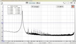
Reading that old thread from 2006-2007 gave me lots of ideas to try, but this was the only successful one. I've attached some more spectra using the C-R-C arrangement.
-Charlie
I scratched my head about what could be causing this for a long time. Was it noise pickup? Was it the transformer? I eventually decided that it must be the harmonics of the sawtooth ripple and noise from the diode bridge. I had tried a C-R-C type capacitor connection previously but had some problems, but I decided to give it a go after trying many other ideas and coming up with no solution.
Sure enough, the C-R-C configuration dramatically reduced the hash and noise. I am using this arrangement:
transformer AC - diode bridge (+) - 10kuF - 1 ohm - 46k uF - (+) rail
transformer center tap - buss bar of 10k uF caps - buss bar of 46k uF caps
transformer AC - diode bridge (-) - 10kuF - 1 ohm - 46k uF - (-) rail
There is no earth ground connection. The "-" indicates a wire connection.transformer center tap - buss bar of 10k uF caps - buss bar of 46k uF caps
transformer AC - diode bridge (-) - 10kuF - 1 ohm - 46k uF - (-) rail
I tried some of AndrewT's suggestions about making a star for the speaker returns "away from the zero volt line of the PS" but this did not improve the situation. Perhaps that would address some other problem that I do not have in my system... not sure.
Reading that old thread from 2006-2007 gave me lots of ideas to try, but this was the only successful one. I've attached some more spectra using the C-R-C arrangement.
-Charlie
Attachments
Post25 shows it well.
Twisted triplet from rectifier to smoothing caps.
Twisted triplet from smoothing caps to Main Audio Ground (MAG).
Not shown as clearly:
twisted pair from mains to transformer.
twisted pair from transformer to to rectifier. If the route transformer to rectifier is long, then the centre tap must also be incorporated into the pair to make a twisted triplet. But the Centre Tap does not stop there it simply passes on through to become the third wire in the rectifier output.
Similarly the speaker return must be the other half of the twisted pair from speaker terminals back to PCB. The Speaker Return does not connect to the PCB. It passes along the output trace route until it meets up with the Power +ve & -ve and then becomes the twisted triplet that came in from the PSU.
ESP shows a Bus Plate for the PSU Zero Volts. I cannot recommend this.
I always locate the MAG OFF the bus plate. I never locate the MAG on the PSU Zero Volts.
Finally. The ESP layout shows neutral following Live. EXCEPT where Live goes to fuse and back. The Neutral could follow as a pair to the fuse and back. But just as good and using less cable the Neutral follows the live until the LIve goes off on itlonely route to the fuse. Here is the trick. The return route from the fuse is twisted with the flow route to the fuse. This twisted pair goes back and is then replaced with the neutral again. In all cases there is a flow and retrun pair for all the mains wiring. from the IEC to the Transformer. Be as scrupulous with ALL signals/currents. Always use twisted pairs for cancellation of radiated fields.
post28:
shows massive improvements.
The no signal condition loses all the mains & harmonics in the noise. I think that peak that hits the -120dB is 180Hz. The third always seems to be the most difficult to remove.
The middle plot shows only low levels of 60, 120 & 180Hz just above the noise.
The left does not help me work out what is happening.
Is there any way to get the noise floor down?
It would help with tying to understand what is happening when the signal and no signal plots are compared.
I wonder if the grass you are seeing when signal passes, is signal correlated noise due to capacitance and inductive coupling brought about by poor trace routing?
Am I correct in assuming that your CRC and moving the MAG off the PSU has brought these improvements, or is there more to it that I have missed/forgotten in preceding posts?
And change the ESP schematic to a link to the ESP site where he shows that schematic.
Unless ESP has given permission for you to post "his" schematic here!
Last edited:
Post25 shows it well.
Twisted triplet from rectifier to smoothing caps.
Twisted triplet from smoothing caps to Main Audio Ground (MAG).
Not shown as clearly:
twisted pair from mains to transformer.
twisted pair from transformer to to rectifier. If the route transformer to rectifier is long, then the centre tap must also be incorporated into the pair to make a twisted triplet. But the Centre Tap does not stop there it simply passes on through to become the third wire in the rectifier output.
Similarly the speaker return must be the other half of the twisted pair from speaker terminals back to PCB. The Speaker Return does not connect to the PCB. It passes along the output trace route until it meets up with the Power +ve & -ve and then becomes the twisted triplet that came in from the PSU.
ESP shows a Bus Plate for the PSU Zero Volts. I cannot recommend this.
I always locate the MAG OFF the bus plate. I never locate the MAG on the PSU Zero Volts.
Finally. The ESP layout shows neutral following Live. EXCEPT where Live goes to fuse and back. The Neutral could follow as a pair to the fuse and back. But just as good and using less cable the Neutral follows the live until the LIve goes off on itlonely route to the fuse. Here is the trick. The return route from the fuse is twisted with the flow route to the fuse. This twisted pair goes back and is then replaced with the neutral again. In all cases there is a flow and retrun pair for all the mains wiring. from the IEC to the Transformer. Be as scrupulous with ALL signals/currents. Always use twisted pairs for cancellation of radiated fields.
post28:
shows massive improvements.
The no signal condition loses all the mains & harmonics in the noise. I think that peak that hits the -120dB is 180Hz. The third always seems to be the most difficult to remove.
The middle plot shows only low levels of 60, 120 & 180Hz just above the noise.
The left does not help me work out what is happening.
Is there any way to get the noise floor down?
It would help with tying to understand what is happening when the signal and no signal plots are compared.
I wonder if the grass you are seeing when signal passes, is signal correlated noise due to capacitance and inductive coupling brought about by poor trace routing?
Am I correct in assuming that your CRC and moving the MAG off the PSU has brought these improvements, or is there more to it that I have missed/forgotten in preceding posts?
And change the ESP schematic to a link to the ESP site where he shows that schematic.
Unless ESP has given permission for you to post "his" schematic here!
Hi Andrew,
Thanks for all of the great routing advice that you wrote above. This is very helpful for me. I had seen "Always use twisted pairs for cancellation of radiated fields." previously, but this spells it out very clearly and in great detail, which is helpful for me (and others) to learn this stuff. I have some 16-3 twisted jacketed power cable that I can probably use for the wiring that will work in this regard. Much appreciated.
You are correct in that the CRC filtering and inserted resistor between PSU zero volt and PCB ground has improved things a lot.
Can't edit/change my post #24 that contains the ESP schematic. I should have posted a link. Maybe a forum mod could fix it...
-Charlie
Andrew,
I think I finally might have a clue about what you are referring to above. See attachment. It's from a very long thread back in 2006 to 2007 (in which you posted often). Someone contributed the schematic. Here is the link to the thread:
http://www.diyaudio.com/forums/solid-state/90728-bob-cordell-interview-power-supplies.html
So is this what you had in mind?
-Charlie
this is all you will ever need........read up on the leach super amp plans.........what i did with my super leach amp is to use a 4mm bolt as single point ground to the chassis....my power amp is dead quiet even with the volume control turned all the way up....
this is the sequence for bolting:
1. power transformer center-tap lead
2. main filter cap ground return leads
3. speaker ground return leads
4. pcb ground return leads
5. input jacks ground return leads, do not ground the input jacks to chassis, use a 4.7~10ohm isolators to earth the jacks locally...
- Status
- This old topic is closed. If you want to reopen this topic, contact a moderator using the "Report Post" button.
- Home
- Amplifiers
- Pass Labs
- AMPLIFIER TESTING: HOW-TO QUESTIONS