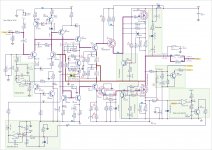
Thank for your time Wahab, there is no point to use this topology for quasy complementary Nfet output stage.The RC circuit which is in paralel with one side of the current mirror
should be suppressed.
Although the amp become instable without it, it is the source
of a hard rail sticking in the negative going of the signal when
clipping occur...
Anyway, i wont go further in simulations, as it s time consuming,
and the design need a complete rework, sorry for apex...
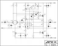
Here is schematics: Auto BIAS and DC ServoArcam Alpha 10 output stage use IRFP360 in quasy complementary configuration, did you have schematics?
Attachments
Did anyone try to implement this auto bias circuit?Here is schematics: Auto BIAS and DC Servo
Regards
In threadapex,
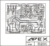
mirror image of this please,
bottom side pcb
regards
http://www.diyaudio.com/forums/solid-state/163159-150w-mosfet-amplifier-irfp250x2-4.html
post #34,
Regards
That feedback have small influence on input impedance.post4.
Is C6, R2 & R8 a bit of +ve feedback to increase the input impedance (bootstrap) or something else?
I must redesign this project, and separate drivers boards, like PC motherboard. Then you can use some old PC case for amplifier,Hello apex, is it possible for you to post the PCB layout and Schematic for your AMP motherboard, it can be extremely useful for many amp projects I guess, thanks a lot, keep up the awesome work")
Regards
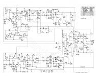
My new project. On motherboard PCB are PSU 0,+/-100V and 0,+/-15V; Soft-Start for X-former; DC and Anticlick speaker protect; Balanced/Bridge circuit and two Amplifier driver who can run all kind output stage Bipolar, Darlington, Mosfet with Complementary or Quasycomplementary circuit.
Can you pls share pcb on this circuit mile?
Can you pls share pcb on this circuit mile?
I will share pcb, but I must finish output stage first.
Regards
waiting for the PCB design.....
Output stage for 'Amplifier Motherboard' work in class E with tracking dawn converter for rail voltages. Rail voltages for outputs is +/-6V DC, and converter increase rail voltage with input signal up to +/-120V DC, and thats mean over 90% efficiency like in class D, but with class AB sound quality.
Power will be 1800W with only 4 pairs of outputs + mosfets for converter.
I will share schematic soon.
Regards
will you share the pcb design??
regards
I will, but I must test amp with converter first (in my free time
),Regards
- Status
- This old topic is closed. If you want to reopen this topic, contact a moderator using the "Report Post" button.
- Home
- Amplifiers
- Solid State
- Amplifier motherboard