D
Deleted member 148505
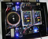
...seems to still be missing a few connections!
Looks good so far.")
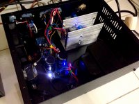
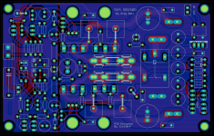
Thanks! Here's the completed amp.
Will be selling unsoldered kit soon
I just ordered ICs and mosfets from mouser, inductors from coilcraft USA. Capacitors are from RS Phils.
Attachments
D
Deleted member 148505
JLAudiophile-250D PCB now comes with pre-soldered SMD parts.
Jlaudiophile 250D 380W 600W IRS2092 Mono Class D Amplifier PCB IRAUDAMP7 | eBay
Jlaudiophile 250D 380W 600W IRS2092 Mono Class D Amplifier PCB IRAUDAMP7 | eBay
Hi JLester87,
I've almost completed the build of your JLAudiophile-250D but I'm confused about something... The BOM calls for 2x 1n4148 but it seems to me that it requires 4
2 under the board between gate resistors r24, r25 as shown in the Assembly Steps
2 on op of the board where printed (1 next to the relay & 1 next to Q105)
Can you please clarify?
Thanks,
D
D
Deleted member 148505
Issue on 1st power up (JLAudiophile-250D)
Hi Lester
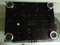
I've just completed the 1st JLAudiophile-250D board and I've connected power for the 1st time (using a bulb current-limiter in series).
The 12v relay seems to operate fine, however there seems to be a short when I connect the +/-45v (voltage and polarity verified). I've checked the polarity of all of the caps and diodes. Do you have any suggestions on what I should be looking for?
I know the SM caps look pathetic (it's my 1st time soldering such small SM components). I tested for shorts though.
Also, do you prefer me contacting you via email for support or is this forum okay?
Thanks,
Darp
Hi Lester
I've just completed the 1st JLAudiophile-250D board and I've connected power for the 1st time (using a bulb current-limiter in series).
The 12v relay seems to operate fine, however there seems to be a short when I connect the +/-45v (voltage and polarity verified). I've checked the polarity of all of the caps and diodes. Do you have any suggestions on what I should be looking for?
An externally hosted image should be here but it was not working when we last tested it.
I know the SM caps look pathetic (it's my 1st time soldering such small SM components). I tested for shorts though.
An externally hosted image should be here but it was not working when we last tested it.
Also, do you prefer me contacting you via email for support or is this forum okay?
Thanks,
Darp
Last edited:
D
Deleted member 148505
Hi Darp,
Please check for shorts in the following components:
1. Output mosfets
2. TIP31C
3. +V, -V, GND
4. Across SMD Caps under the PCB.
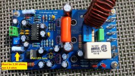
Please check the value of feedback resistor, it must be 120k, 1/4W. I can't clearly see the value in the picture.
The resistor for 5v6 zener must be 3.3k and not 3.3 ohm. Also check if zener is already shorted
Also, you must put the LED directly in the PCB (as shown in the picture). It detects low side gate drive, it might pick up noise if you extend wire into it.
Regards,
Lester
Please check for shorts in the following components:
1. Output mosfets
2. TIP31C
3. +V, -V, GND
4. Across SMD Caps under the PCB.
Please check the value of feedback resistor, it must be 120k, 1/4W. I can't clearly see the value in the picture.
The resistor for 5v6 zener must be 3.3k and not 3.3 ohm. Also check if zener is already shorted
Also, you must put the LED directly in the PCB (as shown in the picture). It detects low side gate drive, it might pick up noise if you extend wire into it.
Regards,
Lester
Attachments
Last edited by a moderator:
Please check for shorts in the following components:
1. Output mosfets
2. TIP31C
3. +V, -V, GND
4. Across SMD Caps under the PCB.
Please check the value of feedback resistor, it must be 120k, 1/4W. I can't clearly see the value in the picture.
No shorts found here and yes, FB resistor is 120k, 1/4W
The resistor for 5v6 zener must be 3.3k and not 3.3 ohm. Also check if zener is already shorted
The zener's not shorted... I was hoping that Digi-key messed up and sent me the wrong value but I checked my order and sure enough, the mistake was my own

I'll get some 3.3k resistors ASAP... Could the incorrect value of the resistor for the 5v6 zeners be causing the rails to short to GND?
Also, you must put the LED directly in the PCB (as shown in the picture). It detects low side gate drive, it might pick up noise if you extend wire into it.
Gotcha. I was planning to wire it to the front of the enclosure. I guess that was a bad idea.
Thanks again,
Darp
Hi again Lester,
I found some 3k48r, 1/4W resistors and threw them in temporarily with the current limiter, just to check... The blue light began to glow, beautifully I'll wait for the correct value before I try further testing.
I really appreciate your help and your prompt reply. I also purchased some of your 1200D boards. I look forward to building them once this project is completed.
Regards,
D
I found some 3k48r, 1/4W resistors and threw them in temporarily with the current limiter, just to check... The blue light began to glow, beautifully
I'll wait for the correct value before I try further testing.I really appreciate your help and your prompt reply. I also purchased some of your 1200D boards. I look forward to building them once this project is completed.
Regards,
D
Last edited:
D
Deleted member 148505
D
Deleted member 148505
D
Deleted member 148505
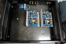
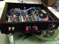
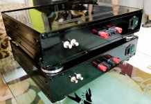
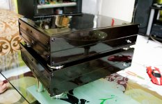
Very nice. What voltage will you be using? As I said I will be running @ approx +/-45v into 2ohms and at times, over 200w RMS... I was thinking that I'll need larger heat sinks than what you show here. Is my assumption correct?
I'll be using +/- 48V DC on those amps.
It depends on the music content that you'll be playing. I assume you'll use it for subwoofer? An angle bar heatspreader is enough if you provide active cooling on it. For passive cooling, you need larger heatsink than the ones in the picture.
Last edited by a moderator:
D
Deleted member 148505
I'll be using them for mid-bass in an active PA setup. Choosing between wiring for 8ohms or 2ohms, I decided to go for 2 because (Correct me if I'm wrong) I figured +/-45v was to low for 200+ Watts 8ohms
Sent from my Nexus 7 using Tapatalk
Yes, you're correct, you'll only get more or less 100w @8ohms with that supply, much lower if the supply sags at full power draw.
Last edited by a moderator:
D
Deleted member 148505
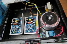
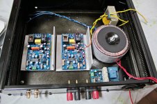
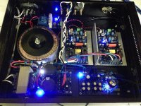
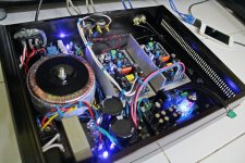
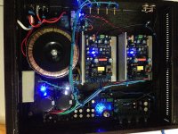
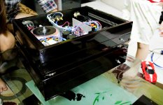
Stereo sound test of JLAudiophile-250D
Total system idle power consumption without tube buffer: 17W
With tube buffer: 28W
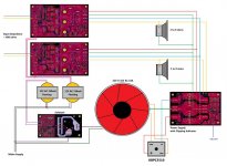
Uses softstart module, psu w/ clip indicator module, and jlaudiophile-250d modules.
The only alien module is the tube buffer.
Sound is superb.
Total system idle power consumption without tube buffer: 17W
With tube buffer: 28W
Uses softstart module, psu w/ clip indicator module, and jlaudiophile-250d modules.
The only alien module is the tube buffer.
Sound is superb.
Attachments
Last edited by a moderator:
D
Deleted member 148505
D
Deleted member 148505
Firstly, Great work!!
I have been watching this thread with great interest and am very interested in the 250D module for an upcoming compact amp build for a den.
Has anyone had time to do a fair comparison for sound quality vs say LJM's modules or for example a TDA895x based module or some of those available from Connexelectronics?
D
Deleted member 148505
Unmodded SKA GB150D with dual source resistors and speaker protection.
Size: 3" x 4.9"
Nice! Will you be selling these? If so, approx how much will it be for a pair of boards?
- Status
- Not open for further replies.
- Home
- Vendor's Bazaar
- Amplifier Modules and PCBs For Sale