Hi,
the diode packs connected to the heatsinks are for temperature compensation of the output stage bias. That sounds OK.
The current in the front end is causing your problem.
10mA at +-85V is causing a dissipation of 850mW in each transistor. That will make them HOT, even with a small sink fitted.
The 0.95V across 100r indicates 9.5mA @ -75V (712mW)
John's running at just above body temp seems to indicate a much lower Iq probably less than 4mA.
John,
could you measure the bias voltages on the resistors on the collectors of the LTP and feeding the base of the CCS i.e. Vr612 Vr613?
Also Vr616 & Vr617?
Thanks Andrew... wait for me to put the lid back on!
Ok, so my amp is obviously biased a bit lower than craigs.
Voltages across R12 & R13 - 1.4v (should be 1.6)
Voltages agross R16 & R17 - 0.85v (should be 0.95)
So about 630mw for TR605 and Tr606 with my 74v Rail, more or less.
The problem with our widely varying mains voltage is that one could bias the amp and 10 min later it can be 10% high or low...
Any thoughts on running off a decent size true sin wave online ups?
Aha!
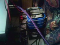
Thats the difference then my heatsinks are about 10x10x27mm and are barely a mm thick. They seem to just clip on with a u- shape over the top of the transistor to hold the back and front on with a bit of force.
I rechecked the measurements and each transistor is dissipating 7xxmW (cant quite remember now) so all is ok, just they probably would like a bigger heatsink.
I am much less worried about this amp now, i think a set of heftier heatsinks will solve the heat worries for me.
The amp measures reassuringly well everywhere else.
Thanks
Craig


Yes, those are definatly going to keep them cooler than the ones in my lab 600, cheers for the pics.
I'll whack in some new heatsinks ASAP.
I had a bit of a listen to the amp tonight, i was pretty impressed with the way it sounded. I agree with what you found, there is a lot of detail and i found i heard bits in the music i didnt know where there before. Such as the sound of the guitar pick tapping on the string, also where the vocals could get harsh (especially through my speakers) they seem to sound more levelled out and natural.
Also the bass has taken a new level in my system, now it is very controlled and has a deeper undertone to it that i have never heard on my music before.
Regards
Craig
No, not bad at all...
I replaced the heatsinks today (scary to be ripping transistors out of a fully working amp) but it worked out ok") .
.
The heatsinks are hot, but easily within comfort to touch now and the bias readings are much more stable.
Excellent!
Thanks again to everyone
Craig
I replaced the heatsinks today (scary to be ripping transistors out of a fully working amp) but it worked out ok
.The heatsinks are hot, but easily within comfort to touch now and the bias readings are much more stable.
Excellent!
Thanks again to everyone
Craig
Hi again,
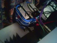
I decided to take AndrewT's advice on upping the supply capacitance for this amp. There wasnt any room inside to add additional capacitors and the replacement ones from electronics suppliers (47/56/68/100000uf) at 100V were too large to fit in the case.
So i took 4x Philips 10000uf 100V caps i had spare and wired them externally via very thick wires.
The amp now has a much more respectable 76000uf of capacitance (i also replaced the bridge rectifier from a 25amp to a 35 amp one to be safe).
havent had oppertunity to crank it up to listen for improvements yet, but theres bound to be at high levels.
Everyone likes pictures...
Regards
Craig
I decided to take AndrewT's advice on upping the supply capacitance for this amp. There wasnt any room inside to add additional capacitors and the replacement ones from electronics suppliers (47/56/68/100000uf) at 100V were too large to fit in the case
.So i took 4x Philips 10000uf 100V caps i had spare and wired them externally via very thick wires.
The amp now has a much more respectable 76000uf of capacitance (i also replaced the bridge rectifier from a 25amp to a 35 amp one to be safe).
havent had oppertunity to crank it up to listen for improvements yet, but theres bound to be at high levels.
Everyone likes pictures...
Regards
Craig
Attachments

Resurrecting an old thread here,
Im planning on replacing the main smoothing caps in this amp as the 2x18kuF@100v ones inside are probably extremely old.
AndrewT mentioned that the capacitance is way to small for 300w RMS per channel into 4R.
So i was thinking maybe 68kuF per rail would help, with such an increase in capacitance from the design will it be a good idea to add NTC's to the primary of the toroid?
Im concerned about the power switch getting stressed on turn on...
(ive already uprated the rectifier to a 400V 35A device)
Hi,
an NTC will make a good soft start. It will also allow you to use a lower value mains fuse.
Consider using a time delayed relay to short out the NTC (try 200 to 500mS). This allows it to cool for the next restart and allows full voltage to the transformer (lower supply impedance).
You can also add NTCs to the power supply rails between the secondaries and the smoothing. Again these should be shorted out with a time delayed relay (try 1 to 3S).
Hi AndrewT
Thanks again, i have just the relays for the job too
I just found these puppies on Farnell
http://uk.farnell.com/jsp/search/productdetail.jsp?sku=1371164
(1 per rail i reckon)
with 76V supply rails theyll be close to the limit but you have to pay so much more for 100V caps .
Ill check out farnell/rs for time delayed relays, i might just DIY'em though
Thanks again, i have just the relays for the job too
I just found these puppies on Farnell
http://uk.farnell.com/jsp/search/productdetail.jsp?sku=1371164
(1 per rail i reckon)
with 76V supply rails theyll be close to the limit but you have to pay so much more for 100V caps
.Ill check out farnell/rs for time delayed relays, i might just DIY'em though
use 555 timers and a few components to trigger the relay.Craig405 said:Ill check out farnell/rs for time delayed relays, i might just DIY'em though
Or do it discretely using transistors etc.
The increase in capacitance won't make a huge difference to the primary start-up current as that is dominated by the transformer inrush current. Is the current transformer a toroid or EI? If it's EI you might get away without a soft start, but it won't hurt to add one.
I have a simple and compact soft-start on my website.
A dedicated soft-start for the caps wouldn't hurt either, but the primary soft-start will help a little.
As a side note, 18,000uF per rail can actually be OK depending on the design of the amp. I know of a 2x 400W into 4 ohm amp that sounds astonishing in the bass with just that amount of capacitance.
- Status
- This old topic is closed. If you want to reopen this topic, contact a moderator using the "Report Post" button.
- Home
- Amplifiers
- Solid State
- amplifier bias drifting