I have not tried doing this but I can't see why it wouldn't work. Use your best judgement to decide to try it or not.
This driver board has a single circuit to shut down all ICs at once. If you lift terminal 2 from the board, you can disable each IC individually by bridging terminals 2 and 3. Then by soldering one of #2 terminals back to the board, you can test to see if one of the 4 circuits is causing the problem.
I'd prefer if you were testing with a low voltage setup but you will have to decide whether it's worth the time to build the supply (simple, #23 on the type-3 page of the latest version of the tutorial).
Unfortunately I don't have the latest updates of your tutorial. Mines a couple + years old now. I'll go scope your site and see what I can do.
I do have a small variable adjustment 12v 1.2a supply... if that'll work. I have time to do whatever it takes to fix this thing all weekend. Thanks sir.
It's 110 AC in 12v variable DC out.
I do have a small variable adjustment 12v 1.2a supply... if that'll work. I have time to do whatever it takes to fix this thing all weekend. Thanks sir.
It's 110 AC in 12v variable DC out.
Last edited:
You'll have to remove the main rectifiers.
Then you need to wrap 4-5 turns around one of the transformers. Use two high-speed rectifiers in series. Connect one end of that winding to the center of the two rectifiers. The other end of the winding goes to the secondary ground.
The output of the two rectifier diodes go to the corresponding rail caps.
I recommend inserting a 12v lamp (1157 or headlamp) as a current limiter. This helps protect the outputs.
What you want is about plus/minus 15-20v on the rails. Adjust the number of turns to get that voltage.
Attachments
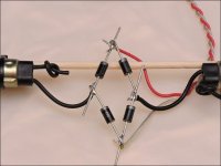
All it takes to make the supply is a length of wire and two diodes. The lamp is recommended but not absolutely required.
A split supply is required.
You would likely benefit from learning to do this. It can save a lot of time and money in an amp that is killing outputs or is otherwise being difficult.
A split supply is required.
You would likely benefit from learning to do this. It can save a lot of time and money in an amp that is killing outputs or is otherwise being difficult.
")
- Status
- This old topic is closed. If you want to reopen this topic, contact a moderator using the "Report Post" button.
- Home
- General Interest
- Car Audio
- Amp protects with or without load.