Hi Everyone!
History:
The install was done by me around 4 years ago. It was working fine for the next couple of years. At some point I gave the car to a relative.
When I got it back, the amp was no longer installed. It was disconnected. Even the fuses were gone.... hahaha. So I placed it back in the box and left it alone, and drove the car without audio.
This weekend I finally had some free time to hook it back up. Installed 3 new fuses and reattached all the wires but…
My amp doesn't work, it is dead
No LED lights on the amp but there is power. 14+ volts on the power line, 12+ volts on the remote/turn on wire, and good ground.
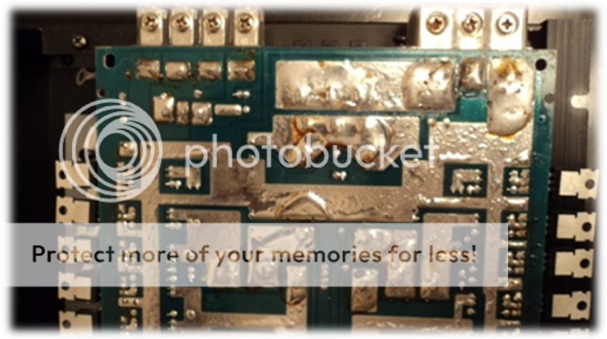
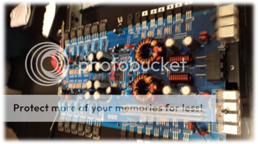
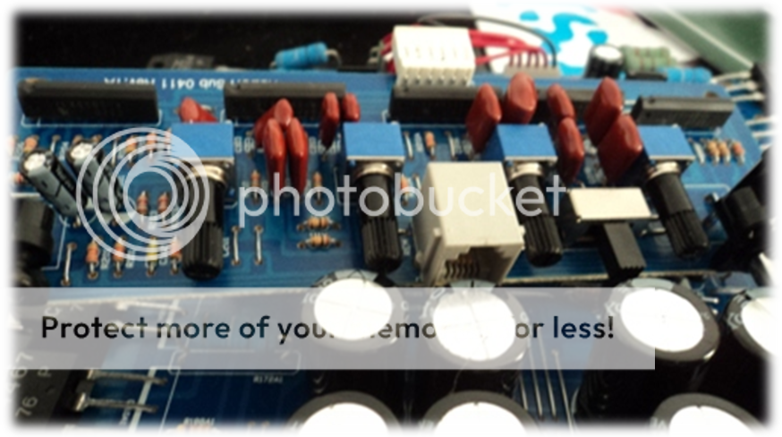
So I disconnected it and brought it into the house. I began reading up on some troubleshooting steps and tried the following below. This is what it looks like opened up on the solder side and front.

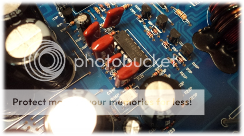
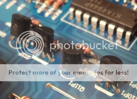
It seems the IC is KIA494AP. I am not sure what the numbers 716 means.
This is the data sheet for the IC KIA494AP datasheet pdf datenblatt - KEC(Korea Electronics) - BIPOLAR LINEAR INTEGRATED CIRCUIT (VOLTAGE-MODE PWM CONTROLLER IC) ::: ALLDATASHEET :::.
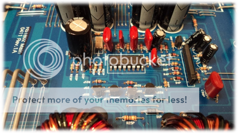
The mosfet is DFP50N06.
The data sheet DFP50N06 - N-Channel MOSFET - DnI datasheet pdf - datasheet.co.kr

My test power supply is a Corsair 750TX.
Some kinda of wire wrapped but it appears the glue rubbed off.
The RCA side of the AMP.
These are the Fuses I am using. Purchased from digikey.

My Digital multimeter is DVM850BL. I set the dial to voltages - range 20.
http://www.vellemanusa.com/products/view/?country=us&lang=enu&id=350297

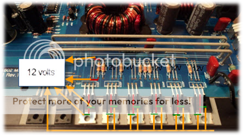
So I hooked up the AMP to the PC power supply, and getting 12 volts on the power terminal. I then loop a wire to the remote/turn on terminal with 12 volts too. The ground terminal is connected to the PC power supply’s ground. Nothing else connected. No fuses, no RCAs connected, and no speakers.
The amp is still not turning on. No LED lights.
I checked the output voltages on the speaker terminals. Left side is .10 Volts and the right side is like 1.07 Volts.
I also checked the output voltages for each socket for the fuses. All of them are producing 10 volts. When I hook up a bulb to each one, it doesn’t light up.

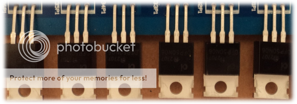
I then checked the mosfets on the power side. I placed the red probe on the middle leg, and placed the black probe on the first and last leg. Each one shows 12 volts I did the same for the next 11 mosfets. All of them are 12 volts. I then checked the resistors next to them. All of them show 12 volts.
I am not sure how to troubleshoot the IC. Or the rectifiers.
I am stump, I have no idea why it is not powering on. Anyone with any suggestions?
Thanks!
History:
The install was done by me around 4 years ago. It was working fine for the next couple of years. At some point I gave the car to a relative.
When I got it back, the amp was no longer installed. It was disconnected. Even the fuses were gone.... hahaha. So I placed it back in the box and left it alone, and drove the car without audio.
This weekend I finally had some free time to hook it back up. Installed 3 new fuses and reattached all the wires but…
My amp doesn't work, it is dead
No LED lights on the amp but there is power. 14+ volts on the power line, 12+ volts on the remote/turn on wire, and good ground.
So I disconnected it and brought it into the house. I began reading up on some troubleshooting steps and tried the following below. This is what it looks like opened up on the solder side and front.
This is the data sheet for the IC KIA494AP datasheet pdf datenblatt - KEC(Korea Electronics) - BIPOLAR LINEAR INTEGRATED CIRCUIT (VOLTAGE-MODE PWM CONTROLLER IC) ::: ALLDATASHEET :::.
The mosfet is DFP50N06.
The data sheet DFP50N06 - N-Channel MOSFET - DnI datasheet pdf - datasheet.co.kr
Some kinda of wire wrapped but it appears the glue rubbed off.
http://www.vellemanusa.com/products/view/?country=us&lang=enu&id=350297
The amp is still not turning on. No LED lights.
I checked the output voltages on the speaker terminals. Left side is .10 Volts and the right side is like 1.07 Volts.
I also checked the output voltages for each socket for the fuses. All of them are producing 10 volts. When I hook up a bulb to each one, it doesn’t light up.
I am stump, I have no idea why it is not powering on. Anyone with any suggestions?
Thanks!
Last edited:
For all DC voltage readings (unless otherwise instructed), place the black probe on the ground terminal of the amp.
Install the fuses.
What is the DC voltage on the three legs of the power supply FET? If they're all essentially the same, you only need to post the DC voltage on the three legs of one FET.
Install the fuses.
What is the DC voltage on the three legs of the power supply FET? If they're all essentially the same, you only need to post the DC voltage on the three legs of one FET.
Thanks Perry!
I set the DMM to DC voltage to 20V and placed the black probe on the chassis ground. There appears to be a wire label "CH GND" screwed to the chassis.
I measured the 12 mosfets on the powered side of the circuit board with the red probe.
Each leg displayed 0.00 volts.
Second time I set the DMM to DC voltage to 200m and measured the 12 mosfets again.
The First legs are 01.1mV
The Last Legs are 01.1mV
The Center Legs always seem to drop down to around 00.4mV
Last edited:
with a fuse installed and black probe on amp ground u must have 12v on middle leg of all power supply transistors .Once u confirm u have 12v on all check for voltage on leg 1 the one on the left side u must have ~5 volts if u have less the power supply is not starting .Also confirm that on pin 12 of the kia494 u have 12 volts .
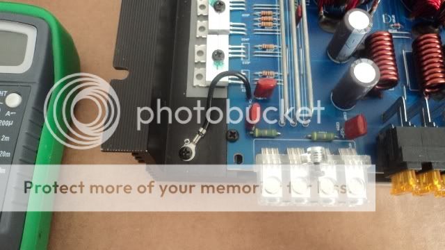
I set the DMM to DC voltage to 20V and placed the black probe on outside ground terminal.
Power Supply Mosfets:
Rectifiers:
Power Supply Mosfets:
All center legs are 12.35V
The rest of the legs are 0.00V
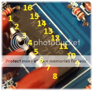
IC - KIA494AP:The rest of the legs are 0.00V
- 1.01V
- 6.67V
- .10V
- .29V
- 0.00V
- 0.00V
- 0.00V
- 0.10V
- 0.05V
- 0.00V
- 0.10V
- 11.68V
- 6.67V
- 6.67V
- 6.67V
- 2.24V
(I believe they are called that). They are the same measurements on the other side too.
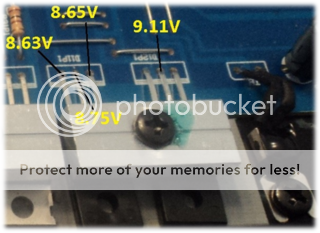
D11P1
- 8.65V
- 8.75V
- 8.63V
- 8.65V
- 9.11V
- 8.63V
I set DMM DC voltage to 20V.
So I traced pin 11 backwards and it connects to a jumper.
So I decided to hook up 18 AWG wire from the remote/turn on terminal to pin 11.
I placed the black probe on the ground terminal on the outside. I measured 12V on pin 11, and 12V on pin 8.
Afterwards, I removed the board from the chassis and observe the circuit trace on the back starting from pin 11.
I believe I cause more damage to the board. I noticed the trace on the board is no longer glued to the PCB. Also, somehow it split into 2 parts too.
So I solder the 18 AWG on pin 11 to the jumper wire. Screwed it back in and measured it again. Same measurements but it is still not turning on.
The mosfet's 1st and 3rd legs are still 0.00V. Center legs are 12V.
Any suggestions? I'll post pics of the damage and rewiring.
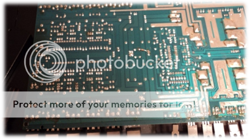
Here is the back side of the board:
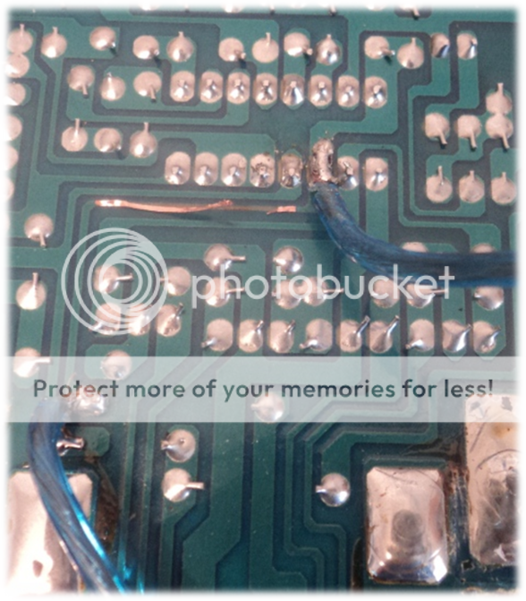
Earlier I placed electrical tape over the wires, and taped the loose traces with tape too. I screwed the board back in and reconnected the B+, ground, and remote terminals. I didn't smell anything burning, or see any smoke. I disconnected the connections to the terminals.
I set DMM to Ohm 20k.
I placed black probe on pin 7 and red on pin 8.
The numbers kept going up. It did not stop.
I set DMM to Ohm 20k.
I placed black probe on pin 7 and red on pin 8.
The numbers kept going up. It did not stop.
Thanks Perry!
I had 12 V on pin 8 and 11. But i blew the mosfets on the left side and it appears i burned another trace on the pcb.
Bah i need to buy parts. What kind of jump wires do i use? I am not sure what size awg.
Gonna order mosfets, them drivers, jumper wires, an ic. Anything else i should add?
I had 12 V on pin 8 and 11. But i blew the mosfets on the left side and it appears i burned another trace on the pcb.
Bah i need to buy parts. What kind of jump wires do i use? I am not sure what size awg.
Gonna order mosfets, them drivers, jumper wires, an ic. Anything else i should add?
Thanks Perry!
I am searching for the parts but unable to find the IC KIA494
I did find KIA494P
Match-a-knob Electronics Wholesale Distributor
I searched TL494 but found TL494CN
TL494CN Texas Instruments Voltage Mode PWM Controllers
I am guessing TL494CN can be considered a good substitute ? They seem to match.
I having a hard time figuring out a substitute for the mosfets DFP50N06.
Any suggestions? Thanks!
I am researching a couple more parts.
I am looking to replace a1266, which I believe are drivers? It comes back as a possible PNP TRANSISTOR EPITAXIAL.
A1266 datasheet, A1266 datasheets, A1266 datenblatt, A1266 manual, A1266 data sheets, A1266 pdf - ALLDATASHEET.COM
Closes I found is a BD139 Transistor. Is this a good substitute?
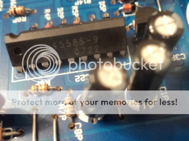
Also, I was observing another IC, IL4558S-9. It appears to be a Dual Operational Amplifiers.
Datasheet:
IL4558S-9 pdf, IL4558S-9 description, IL4558S-9 datasheets, IL4558S-9 view ::: ALLDATASHEET :::
It is a SIP-9 design. I have like 5 of these on the board but I am looking at the one near IC 494.
I found other similar OP AMPs like KIA358S, KA1458S, or KA458S but all these appear to be obsolete. Is SIP-9 also obsolete? I found a ton of 8 DIP designs.
What would replace an IL4558S-9 SIP-9 IC?
Thanks!
I am looking to replace a1266, which I believe are drivers? It comes back as a possible PNP TRANSISTOR EPITAXIAL.
A1266 datasheet, A1266 datasheets, A1266 datenblatt, A1266 manual, A1266 data sheets, A1266 pdf - ALLDATASHEET.COM
Also, I was observing another IC, IL4558S-9. It appears to be a Dual Operational Amplifiers.
Datasheet:
IL4558S-9 pdf, IL4558S-9 description, IL4558S-9 datasheets, IL4558S-9 view ::: ALLDATASHEET :::
It is a SIP-9 design. I have like 5 of these on the board but I am looking at the one near IC 494.
What would replace an IL4558S-9 SIP-9 IC?
Thanks!
Last edited:
- Status
- This old topic is closed. If you want to reopen this topic, contact a moderator using the "Report Post" button.
- Home
- General Interest
- Car Audio
- AMP not Powering On (56k Warning)