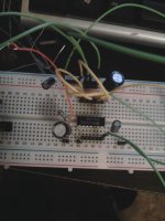
Alright well I just went ahead and bought both 470uF and a 6800uF (what was on hand) cheapo electrolytic caps. Yes I have read these are terrible to put in the signal path but for testing they are equally terrible and adequate. I noticed very little difference between the two caps on this setup which proves to me its fine.
One unintended thing... it picks up the oldies station with a 3.5mm plugged in.
One unintended thing... it picks up the oldies station with a 3.5mm plugged in.
Last edited:
You don't like oldies? ")
The filter doesn't have to be that low. Try the handiest picofarad cap you have. Was anything connected to the other end of the plug? If not it'd be more likely to act as an antenna.
Remember also that if you decide on the bridged circuit the series output cap is a moot point.
The filter doesn't have to be that low. Try the handiest picofarad cap you have. Was anything connected to the other end of the plug? If not it'd be more likely to act as an antenna.
Remember also that if you decide on the bridged circuit the series output cap is a moot point.
Yea connected or not I got the radio station. A little bit of volume on the computer and it would mask it but the second it went quiet I could hear a quiet rendition of "Thriller". I'll grab a little pF cap tomorrow and give it a go.
The final build will be an auto grade 50W Toshiba chip amp. Just ironing out the theory before I order one of those. Burnt one chip so far so its a good thing.
I'll grab a little pF cap tomorrow and give it a go.The final build will be an auto grade 50W Toshiba chip amp. Just ironing out the theory before I order one of those. Burnt one chip so far so its a good thing.
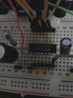
So I tried an RF snubber tonight. It kinda just adds a TON of noise... I mean you cant hear the RF anymore because of the chainsaw noise but that's hardly the effect I was thinking. How sensitive is this circuit? With resistors on hand I can do 2.2 ohm and 2.8 ohm (pair of 5.6 in parallel) but neither sound anywhere near good. Me being near it makes it worse so somehow my snubber is causing more EMI interference?
You don't show any input leads. (edit: nevermind that, my navigation was off) Using shielded wire there, and cleaning up the other wiring, is my best suggestion. Long & loopy wires invite RFI.
You could also try the simplest configuration of output capacitor only, verify it, and add to it while testing at each step. That should automatically localize noise and other effects on the circuit.
You could also try the simplest configuration of output capacitor only, verify it, and add to it while testing at each step. That should automatically localize noise and other effects on the circuit.
Last edited:
Well at any rate this little chip is a fun science project but it is only 2.5W and even the best of speakers powered at 2.5W will barely overpower a noisy late 60s VW engine. lol
So lets discuss the TDA1557Q. Mouser claims NXP has discontinued this chip with no replacement so is it common to buy them from ebay sellers?
Then pin 12:
I think I've seen this discussed somewhere but hardly remember if an answer was ever offered up. "the harmonic distortion at low frequencies can be decreased by connecting two diodes to ground at pin 12." Can anyone expound on this? I'm imagining going to my local electronics store, picking a couple of their cheapest garden variety diodes off the shelf and hooking them to pin 12 in the direction of ground. Am I close?
Just making sure:
This chip has "speaker protection" so that means I don't need a speaker coupling cap, right?
That IC will deliver10 to 12 W into 4 Ohm, and whether it is louder than the car depends on the speaker sensitivity.
Speaker protection does not have to do with the DC blocking cap. You don't need the cap, because it is a BTL configuration. The speaker protection only works as long as the IC is OK. If one of the output transistors blows, it will not help.
Speaker protection does not have to do with the DC blocking cap. You don't need the cap, because it is a BTL configuration. The speaker protection only works as long as the IC is OK. If one of the output transistors blows, it will not help.
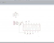
Okay so I got a couple TDAs in the mail. Working on designing a PCB to make things simple. Attached is my schematic so far.
Cap in audio signal is planned to be:
http://www.mouser.com/ds/2/315/ABD0000CE29-44537.pdf
Resistors:
http://www.mouser.com/ds/2/427/cmfind-111261.pdf
and cap on the power lines will just be a generic ceramic.
How's it look?
Cap in audio signal is planned to be:
http://www.mouser.com/ds/2/315/ABD0000CE29-44537.pdf
Resistors:
http://www.mouser.com/ds/2/427/cmfind-111261.pdf
and cap on the power lines will just be a generic ceramic.
How's it look?
Attachments
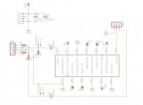
I think I came up with an elegant (read overly complicated) implementation.
Defaulty R4 is not installed and the radio operates in Mono mode with jumper SV2 on pin 1 and 2.
However if you remove R1-4, jumper R1, jumper from the connector side of R2 to the far side of R4 and set the jumper SV2 to pin 2 and 3 you enable stereo.
X1 and X3 are there so if I ever get a proper switched two channel pot I can wire up a quick loom between X1 and X3 and it. Or in mono a switched single pot can be connected to X1. Otherwise the connectors can have a short jumper there and volume control only on the connected device.
Attachments
Last edited:
- Status
- This old topic is closed. If you want to reopen this topic, contact a moderator using the "Report Post" button.
- Home
- Amplifiers
- Chip Amps
- Amp newbie attempting project