Hi tube freaks,
i have been tweaking in my amp= now it doesn't work.
Lat time i blew a condenser and i said to myself:you won't be touching it again but ....
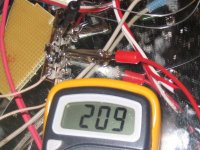
What i did was change the power supply and resolder a few resistors. No power now...no wonder only 8v in the anode. Before the last resistor(anode one) i read 235V, once it passes through the 100K anode resistor multimeter(a new one) says 8V. Surprised it still sounds( low volume) but as bad as my PC soundcard.
Possibly is the new power trafo which was handwound...and hasn't got the power...but why it waits until the last resistor to drop?
Could it be something else? The last condenser? A short in the valve socket? Amp has only one valve. Monoblock.
How much juice a PCL86 se monoblock needs?
p.s. some people may be tempted to advice me against high voltage dangers seeing that i'm a newbie...i appreciate it but don't waste your time...i don't respect 230V anymore, i have taken several shocks and it's ok... i write faster now (this is a joke). Serious now, i would never attempt to build a 400V one.
But please tell what voltage really kills?
i have been tweaking in my amp= now it doesn't work.
Lat time i blew a condenser and i said to myself:you won't be touching it again but ....
What i did was change the power supply and resolder a few resistors. No power now...no wonder only 8v in the anode. Before the last resistor(anode one) i read 235V, once it passes through the 100K anode resistor multimeter(a new one) says 8V. Surprised it still sounds( low volume) but as bad as my PC soundcard.
Possibly is the new power trafo which was handwound...and hasn't got the power...but why it waits until the last resistor to drop?
Could it be something else? The last condenser? A short in the valve socket? Amp has only one valve. Monoblock.
How much juice a PCL86 se monoblock needs?
p.s. some people may be tempted to advice me against high voltage dangers seeing that i'm a newbie...i appreciate it but don't waste your time...i don't respect 230V anymore, i have taken several shocks and it's ok... i write faster now (this is a joke). Serious now, i would never attempt to build a 400V one.
But please tell what voltage really kills?
Hi,
Have you measured that resistor already?
As far as I'm concerned: ANY voltage.
Cheers,")
SAFETY
once it passes through the 100K anode resistor multimeter(a new one) says 8V.
Have you measured that resistor already?
But please tell what voltage really kills?
As far as I'm concerned: ANY voltage.
Cheers,
SAFETY
Thanks for the reply fdgrove...now i know more, it's not the power trafo. I've plugged it to line and i guess if it can drive a microwave certainly could drive my amp.
The resistor is Kiwame and it reads exactly 100K Frank.
I suspect of the valve socket so i'm going to check.
I will read the safety measures.
The resistor is Kiwame and it reads exactly 100K Frank.
I suspect of the valve socket so i'm going to check.
I will read the safety measures.
The valve socket seems to be ok...i don't get it. Forgot to say earlier that when connected to my house 230V line the plate read 24V. An improvement!!!! From line to anode there's the ss bridge, a 47 uf cap followed by a 330 Ohm resistor followed by a 100 uf cap followed by a 47k resistor followed by a 47uf cap and a final 100K resistor to plate. The voltage goes right until the final resistor but it reads ok so....
Now i'm lost and don't know what to check. At my wit's end.
Now i'm lost and don't know what to check. At my wit's end.
schematic? i have post it mant times...bored
the clue is here: as the filaments heat up the voltage drops slowly....Have 2 power suplies now and the plate reachs to 280V which is the correct value but when i switch on the filaments supply the voltage drops slowly to 140V. Yes before the drop was to 8V but i did rewire everything and found a mistake....had a 220 ohms cathode resistor in the triode input instead of the 330 Ohms which is the value that appears in the schema. That may be what has raised the voltage...so if put a bigger resistance in the cathode will i get more volts? The amp was working well with the original schematic. The 330 ohm resistor was there before and the amp worked at full potential now it doesn't.
Everything is ok so i must assume my OT went wrong. I have tried different valves and still the same problem.
What can it be?
I have checked all the resistors,they're ok. Could it be a faulty condenser?
Hi,
Just disconnect it and measure the voltages again.
Cheers,
Everything is ok so i must assume my OT went wrong.
Just disconnect it and measure the voltages again.
Cheers,
Good Karma!!!
I have the feeling the ss bridge may be the cause....going to replace it now. John you are right...i was a bit stupid but i had the feeling the schema wouldn't help here and i have post it several times so i assumed ppl were already sick of seeing it....
Karma how did you find the leaky cap? Did you change one by one? Well i am going to work a little and stop the questions.
Thanks to all...and dhaen sorry for being rude...must have been solder fumes...
it was kinda small needed more power for when it warmed up
just a bigger value
one of the rectifier's was the main problem. for me
my iron has 240 + 240 it was only working on one. it was a small
tranny so i needed all the power i could get from it
no leaky's cap's that i could find
for you when it warm's up it draw's more current. so ya i would be looking at the power supply.
good luck..........
dont forget to discharge it.
changed the bridge, some caps....the same
went back t frank's advice and removed the OT from the circuit....only 20 Volts mor 140 less than it should be.
I know it's not the power trafo but as my home's supply is 230v same as my tube circuit needs i did try that again....same result....goes down, down and down.


the coupling cap? or the gun?
not sure i would need to see the schematic.
here's a small search it may have something u can use
http://www.diyaudio.com/forums/showthread.php?threadid=33311
cheer's
here's a small search it may have something u can use
http://www.diyaudio.com/forums/showthread.php?threadid=33311
cheer's

Hi,
Alk,
Surely it must have something to do with to PS, probably one or more diode(s):
-you have 280VDC, your target voltage when the tubes are warmed up, when the tubes aren't heated.
This should be considerably higher as no current is flowing. It's as if they're not there.
So, the 280VDC could incidentally happen to correspond to what you'd expect to see with the circuit functioning normally.
-OPT removed, voltage goes up a little: normal.
-Assuming a diode is disconnected or dead the net result is close to what you're measuring and I suspect a high ripple level on the PS as well since it could mean the full wave bridge now works similar to a capacitively loaded full wave rectifier...
-If one of the PS caps is quickly losing its charge the voltage should get high first, then it would keep on dropping untill it stabilises to whatever charge it can still hold.
Either way, if you have replacement diodes and caps, I'd try them first then measure the ones you pulled to see which is faulty.
Cheers,
Thanks all for you help:
Karma thxs for the lnk i've read that before in my opinion SS bridges sound quite good. Still student no budget for tube rectifying.
v-man that would have been too easy.
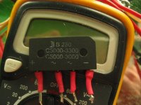
Frank what is a capacitively loaded full wave rectifier? Seems i have one of those. Anyway was that the problem or is a new one? In the pic you can see the prior bridge and the new one which was made in a hurry but it's correctly wired. Should give 285 Volts. Maybe i did burn a diode...but what did burn the first one? Well tomorrow i'll buy more diodes and check again.
Yes Daehn that's the one.
Good night to all i go to sleep a bit frustated ....
my tube amp is not well...
Cheers
Karma thxs for the lnk i've read that before in my opinion SS bridges sound quite good. Still student no budget for tube rectifying.
v-man that would have been too easy.
Frank what is a capacitively loaded full wave rectifier? Seems i have one of those. Anyway was that the problem or is a new one? In the pic you can see the prior bridge and the new one which was made in a hurry but it's correctly wired. Should give 285 Volts. Maybe i did burn a diode...but what did burn the first one? Well tomorrow i'll buy more diodes and check again.
Yes Daehn that's the one.
Good night to all i go to sleep a bit frustated ....
my tube amp is not well...Cheers
Attachments
Hi,
The type of rectification shown in your diagram with the PCL86 is a capacitively loaded full wave bridge rectifier (FWB or Graetz bridge). It's the most efficient type as it wastes the least voltage and current.
It also rectifies the full cycle of AC coming from the xformer as opposed to a half-wave rectifier.
Here's a document from Hammond :
HAMMOND
Cheers,
Frank what is a capacitively loaded full wave rectifier?
The type of rectification shown in your diagram with the PCL86 is a capacitively loaded full wave bridge rectifier (FWB or Graetz bridge). It's the most efficient type as it wastes the least voltage and current.
It also rectifies the full cycle of AC coming from the xformer as opposed to a half-wave rectifier.
Here's a document from Hammond :
HAMMOND
Cheers,
- Status
- This old topic is closed. If you want to reopen this topic, contact a moderator using the "Report Post" button.
- Home
- Amplifiers
- Tubes / Valves
- amp in trouble