The polarities are okay. Where is the wire to the transformer's center tap at the point you designated as 'Transformer (-)'?pra3718 said:Please find the polarities.
That is a split power supply, which will give you ±15,5 V. The TDA1554 cannot be used with that power supply. It needs a single power supply. Either, what you are building now or better with a transformer with a single secondary. The latter would mean to buy a different transformer.pra3718 said:When I was searching on the NET I got one more PSU circuit. It is simlar to yours. Should I go with this ? Only Caps I will use 4700 uf . There is change of Caps setting. Pl. find attached picture.
No. This circuit would do nothing. You need capacitors and resistors to make filters. Start with this site to find out, how passive crossovers work. Then read about the design of an active low-pass filterpra3718 said:You were posted about crossover I altered one crossover to fit my need. Actually I need to improve my sub's signal.
Pl find attached file. Is this circuit would improve my sub signal ?
Actually Transformer (-) wire I have removed for my previous PSU style. (I did not have short wire) For wiring purpose pl refer my previous posted picture. You had to find the polarities thats why I post like this.
I will make complete PSU as per your design. If there is any problem I will post complete picture again.
Thank you.
I will make complete PSU as per your design. If there is any problem I will post complete picture again.
Thank you.
Is your power supply already working? If not, you won't get more power out of it., and a preamp won't help.
Also check, if all speaker polarities are correct.
http://sound.westhost.com/project88.htm
Also check, if all speaker polarities are correct.
http://sound.westhost.com/project88.htm
My power supply is not working. I was stick with my old-style PSU. But yesterday I tried agin the same schematic posted by you. Problem remain same. i.e. not working.
Your power supply involed 1 Transformer, 8 diods, 2 Capacitors which is not working for me.
I just altered your power supply 1 Transformer, 4 diods, 2 Capacitors which is working.
Pl. do any correction which is required for me. & Your are right my new altered PSU has more power. If I use both 12+ it may increase more power.
Please find attached files.
I know the speaker polarities but don't know TDA1554q (+)(-) the output pins are 6&8 for tweeter & 12&10 for woofer. Or pl. guild how to connet the speakers.
Thanks & Regards.
Attachments
Yes, my fault. It will not work with a center-tapped transformer like the one you have. It would with a dual secondary transformer, but it would be even easier with one of those, because you can simply connect the secondaries in parellel before one rectifier bridge.pra3718 said:My power supply is not working. I was stick with my old-style PSU. But yesterday I tried agin the same schematic posted by you. Problem remain same. i.e. not working.
That is the point. You are now using only half of the transformer. It will not be able to deliver its full power that way, but there is no way to change that other than using a different transformer. The best choice would be a single secondary 12 V with 10 A or more.pra3718 said:Pl. do any correction which is required for me. & Your are right my new altered PSU has more power. If I use both 12+ it may increase more power.
Pins 6 and 12 are (+), pins 8 and 10 are (-).pra3718 said:I know the speaker polarities but don't know TDA1554q (+)(-) the output pins are 6&8 for tweeter & 12&10 for woofer.
There are several tests for correct polarity.
1) Connect a small battery to your speaker and watch the membrane. With battery plus to speaker plus the membrane will move outward.
2) Connect only two speakers. Set them up so that they have the same distance to your ears. Play pink noise. If the polarities are the same, the noise will come from the center between them. If the polarities are different, the noise will be off center.
Cross-overs and different distances from the speakers to your ears can also influence the phase. Due to that it can sometimes be better to connect the subwoofer the wrong way round. That is why subwoofer amplifiers often come with a phase or polarity switch. Trial-&-Error is the easiest way to check that. There will be one way, which will improve the sound significantly.
Thanks for you reply.
First of all my PSU. your BRIDGE concept is good than my previous style bcoz IT IMPROVES SOUND QUALITY SPECIALLY BASS. So I wish to use BRIDGE concept. But you know I have center-tapped transformer as you posted
<but it would be even easier with one of those, because you can simply connect the secondaries in parellel before one rectifier bridge.>
So pl. post how to use center-tapped transformer with bridge concpet. Pl. post schematic.
Thank you & Regards.
With a center-tapped transformer it is either your first schematic that gives you half the transformer voltage = quarter possible output power or your latest schematic, which gives you half the transformer current = third to half possible output power.
Ways to improve your power supply are
- use a bigger transformer, preferably single secondary 12 V and more than 15 A.
- use more and/or bigger smoothing capacitors.
- connect 100 nF ceramic capacitors from pins 5 and 13 of each IC to ground.
One more way to improve the bass performance is to replace the 220 nF input capacitors on the subwoofer channels with a 1 µF or bigger MKP (MKS) capacitor or a 10 µF or bigger electrolytic (positive side toward IC).
Try to replace those 220 nF capacitors with small values between 220 pF and 2,2 nF MKP on the tweeter channels as long as you don't have a real crossover. That way you relieve them and the corresponding amplifier channels of useless low-frequent signals. 1 nF or 1,5 nF should be a good starting value for a dome or cone tweeter. For piezo or foil tweeters start with 330 pF or 470 pF.
I think it's a last question for PSU
OPTION 1 : full transforer use, two diod & two capacitor
OPTION 2 : half transformer use, four diod & two capacitor
Which option I should final.
Pl. refer your last post # 25 < Is your power supply already working? If not, you won't get more power out of it., and a preamp won't help. >
Still I did not work on preamp/crossover. So which OPTION of PSU would drive preamp/crossover confortably.
Already connected 100 nF ceramic capacitors from pins 5 and 13 of each IC to ground.
Actually I don't have real crossover but I have already developed filter as under.
NOTE : To all IC, input capacitor already mounted 10mfd 25v
IC1:A: = For tweeter : Palyers Signal goes through 0.01 Ceramic capacitor -> 10K Resistor to Ground -> 0.01 Ceramic capacitor -> 10mfd 25v Input Capacitor
IC1:B: = For woofer : No filteration.
Pl. find picture for tweeter filteration.
In fact I am happy with all Mid & Tweeter sound accept SUB.
Attachments
You said yourself that option 2 sounded better.pra3718 said:I think it's a last question for PSU
OPTION 1 : full transforer use, two diod & two capacitor
OPTION 2 : half transformer use, four diod & two capacitor
Which option I should final.
With the passive filters you use now, you don't need any. If you want to use active filters, the power supply from post #20 with voltage regulators added will be the right solution. You need a center-tapped transformer like the one you have or a dual secondaries transformer, but much smaller power rating is sufficient. E. g. 2*12 V or 2*15 V and something between 3 and 10 VA.pra3718 said:Still I did not work on preamp/crossover. So which OPTION of PSU would drive preamp/crossover confortably.
10 mF or 10 µF?pra3718 said:NOTE : To all IC, input capacitor already mounted 10mfd 25v
That should only be for the subwoofers, but did you notice any improvement?
The 10 mF or µF capacitor is of no use here. 0,01 is that 10 nF or 10 pF? I assume nF for the following. The first capacitor and the 10k to ground form a filter with 1591 Hz corner frequency. The second capacitor and the input resistor inside the TDA1554Q (60k) form a filter with 265 Hz corner frequency. The first capacitor should probably be bigger, the second capacitor should surely be bigger, but without knowing the exact speaker type you use it is all guesswork.pra3718 said:IC1:A: = For tweeter : Palyers Signal goes through 0.01 Ceramic capacitor -> 10K Resistor to Ground -> 0.01 Ceramic capacitor -> 10mfd 25v Input Capacitor
The topology could be similar to the tweeter filter, but resistors and capacitors change places and you add another capacitor to ground behind the second resistor. Try 10k in series - 100 nF to ground - 10 k in series - 160 nF to ground - TDA. The bigger the capacitors, the lower the crossover frequency. If that filter works, attenuate all other channels, because the woofer will need more power for the same sound pressure level. Then experiment with the polarity and positioning of the woofer.pra3718 said:IC1:B: = For woofer : No filteration.
Input capacitors are 10uf 25v to all IC. (Subwoofer & Tweenter)
High-pass capacitors are 0.01uf (as I asked to my supplier) ceramic capacitors.
This kind of passive filter (before amplifing) I can develope in many variations. But you know this kind of filter losses the singal specially in LOW Frequency. Then how to increase the loss of the signal? I found buffer amp which can increase the signal.
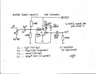
Already you have provided good information on this subject. OPA134 is not available in my place. NE5532 is available & I found buffer circuit as attached picture. This circuit is good but the problem is the spekar goes up-down (with OR without) sound.
The circuit is 12V & my psu is 15V approx. If it is the problem then you are requested to make any required correction to the circuit.
Or if you have better option for increase signal using NE5532 Please post.
waiting for you post.
Thanks & Regards.
High-pass capacitors are 0.01uf (as I asked to my supplier) ceramic capacitors.
This kind of passive filter (before amplifing) I can develope in many variations. But you know this kind of filter losses the singal specially in LOW Frequency. Then how to increase the loss of the signal? I found buffer amp which can increase the signal.
Already you have provided good information on this subject. OPA134 is not available in my place. NE5532 is available & I found buffer circuit as attached picture. This circuit is good but the problem is the spekar goes up-down (with OR without) sound.
The circuit is 12V & my psu is 15V approx. If it is the problem then you are requested to make any required correction to the circuit.
Or if you have better option for increase signal using NE5532 Please post.
waiting for you post.
Thanks & Regards.
Attachments
That is exactly, what it shall do. It filters low frequencies out, so that e. g. the tweeter does not have to make movements that could destroy it. It would be nonsense to counteract that loss. What you should do is to optimize the crossover frequencies. Experiment with different capacitor values to find the combination that harmonizes best with your speaker combination. Also attenuate the different amplifier channels so that all speakers reproduce at the same sound pressure level.pra3718 said:But you know this kind of filter losses the singal specially in LOW Frequency.
Start with the woofers unattenuated and the tweeters and subwoofer fully attenuated. Then turn the volume of the tweeters up until you get a harmonic sound. When you are satisfied with the result, turn up the volume of the subwoofer until you can discern the subwoofer as a separate source. Then turn it back down until you just cannot discern it as a different source anymore. Make a test, switching the subwoofer on and off. The sonic balance should not change, e. g. a voice should still sound the same and should not become unnatural, when the subwoofer is on. The effect should be that you notice something is missing, when the subwoofer is off, but when the subwoofer is on, the bass should not sound exaggerated. Without measuring equipment, people tend to adjust the subwoofer too loud. After sufficient listening time it starts to bother and the subwoofer will be attenuated further.
A buffer will not increase the signal. It will only stabilize it, when the load is too demanding. That is not the case with your amplifier.pra3718 said:I found buffer amp which can increase the signal.
If you use an op amp and a passive filter, you already have the components for an active crossover.
I am not sure, if I understand this correctly. Do you mean to say that the speaker is moving all the time? If so, then it is probably the combination of unregulated power supply and rail splitter resistors. The ripple from the unregulated power supply will pass through the upper 100k resistor into the non-inverting input of the op amp, which will deliver it to the input of the TDA. So you will probably have a continuous 100 Hz signal on your speakers. If the signal is strong enough, you should be able to hear it as a humming or buzzing noise. If you don't hear it, it is either too weak, or your woofers are out of phase and the signals cancel each other out.pra3718 said:This circuit is good but the problem is the spekar goes up-down (with OR without) sound.
The cure would be to supply the op amp from a regulated power supply.[/B][/QUOTE]
This becomes interesting.
With reference to recent post & PART I (TUNE the all channel with each other)
I wish to tell you the real picture.
IC1 Stereo) for Tweeter & Woofer (LEFT)
IC2Stereo) for Tweeter & Woofer (RIGHT)
IC3Stereo) for full range REAR both Speakers
IC4Stereo) two Subwoofer Driver. (Not using CENTER)
All amps are connected with all speakers. Ok. You know when Power switch ON. DVD Player with Amps start sounding with its default volume level.
FRONT (Left/Right) speakers are more LOUD (Due to Two IC)
REAR (Left/Right) speakers are less LOUD (Due to single IC & players low single compare to front)
SUBWOOFER (two speakers are more less LOUD) (Due to single IC & Players even low single.) This is the problem which I want to increase) I have checked all channel signal of the Player with small speaker individualy and found above data. i.e Signal level.
Now you said I should put individual volume control for each channel & Set each volume level as per need. Ok.
I wish to do is.. Not to minimise to Volume of the front speaker to match to rear & sub. I want to increase the volume for low singal. Please try to understand me. Ok. For that purpose I need (SIGNAL INCREASER AMP.)
Now I understood that Buffer is useless for me. So I want amplifier which would RUN BEFORE my TDA1554q While serching the NET I found something
NE5532, TDA2320A, LM386, LA4425A, TDA1522 etc.
One of those amp how to use with single power supply ? If you have schematic please post.
Thank you.
With reference to recent post & PART I (TUNE the all channel with each other)
I wish to tell you the real picture.
IC1
Stereo) for Tweeter & Woofer (LEFT)IC2
Stereo) for Tweeter & Woofer (RIGHT)IC3
Stereo) for full range REAR both SpeakersIC4
Stereo) two Subwoofer Driver. (Not using CENTER)All amps are connected with all speakers. Ok. You know when Power switch ON. DVD Player with Amps start sounding with its default volume level.
FRONT (Left/Right) speakers are more LOUD (Due to Two IC)
REAR (Left/Right) speakers are less LOUD (Due to single IC & players low single compare to front)
SUBWOOFER (two speakers are more less LOUD) (Due to single IC & Players even low single.) This is the problem which I want to increase) I have checked all channel signal of the Player with small speaker individualy and found above data. i.e Signal level.
Now you said I should put individual volume control for each channel & Set each volume level as per need. Ok.
I wish to do is.. Not to minimise to Volume of the front speaker to match to rear & sub. I want to increase the volume for low singal. Please try to understand me. Ok. For that purpose I need (SIGNAL INCREASER AMP.)
Now I understood that Buffer is useless for me. So I want amplifier which would RUN BEFORE my TDA1554q While serching the NET I found something
NE5532, TDA2320A, LM386, LA4425A, TDA1522 etc.
One of those amp how to use with single power supply ? If you have schematic please post.
Thank you.
pra3718 said:Already you have provided good information on this subject. OPA134 is not available in my place. NE5532 is available & I found buffer circuit as attached picture. This circuit is good but the problem is the spekar goes up-down (with OR without) sound.
The circuit is 12V & my psu is 15V approx. If it is the problem then you are requested to make any required correction to the circuit.
Or if you have better option for increase signal using NE5532 Please post.
hello.
tda 1554q is for use with battery power(12v,cars) or regulated power supply.unreg. suuplies can cause problems.........
the bufferamp has a voltage gain of 1 (doesn't increase the outputvoltage).
the buffer works with e.g. 6v.............to 30v single supplyvoltage,but you should use it with a reg. supply (if you have 15v unreg. s. you may use a 12v regulator,like 7812,78L12,.......).
for more gain you can build an non inverted amp with this (2 res and a cap............connecting output with inv. input............)
greetings...................
A simple 10k logarithmic potentiometer before the filters will be sufficient for that task on all channels you want to attenuate.pra3718 said:Now you said I should put individual volume control for each channel & Set each volume level as per need. Ok.
I already did that in post #25. You will have to adapt it to your needs. The site comes with a table for different gains. It is possible to work with one gain stage only. For that you combine the left half of figure 2 with the right half of figure 4. You can replace the OPA2134 with any op amp you like, e. g. the NE5532.pra3718 said:One of those amp how to use with single power supply ? If you have schematic please post.
And this is an example for a fitting power supply. For your current steup it would be good to use only the upper half of it, from GND upward. Then you need to add two 100k resistors like in the buffer you posted as rail splitter for the op amp input. You can use a lower voltage regulator to match your transformer, e. g. 7812/7912 or 7810/7910.
Thank you pacificblue
< potentiometer before the filters >
potentiometer Worked for me. !!! I AM HAPPY !!! All channels sounding with equal pressure level. Now overall sounding good. SORROUND EFFECTS IS ALSO IMPROVED. Many peoples used MONO-IC for each channel. But using stereo IC for each channel, I can drive Woofer/Tweeter best way with pre-filter frequency.
Thanks again.
Regards.
( ONLY ONE THING BALANCE NOW SUBWOOFER )
Signal boosting is a BIG problem for me. But I am trying with your provided information.
Pacificblue, Mjf both of you have provided good information but still I could not make audio signal booster. As you have posted schematic for Buffer Amplifier, you are requested to post Signal booster (with lot of gain) amp Schematic. (using NE5532 & present PSU if possible)
Sir, I am working for audio signal booster from last 10 days.
Thanks & Regards.
Sir, I am working for audio signal booster from last 10 days.
Thanks & Regards.
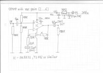
hello.
this is an opamp with variable gain (2.......to r.a. 6 times) -more than enough.....if not there could be something wrong with your system.
most parts are free to choose..........
7812 is a standard regulator with 12 v out (lm7812.....).you can also use a 7810 ................
the decoupling caps(47n......100n) should be solderd near by the pins of the opamps.
adjust the gain with the 10k trimmpot to your system.........
greetings...................
Attachments
- Status
- This old topic is closed. If you want to reopen this topic, contact a moderator using the "Report Post" button.
- Home
- Amplifiers
- Chip Amps
- Amp in sub encloser with fan