I prefer this one,
Its the ACF aikido PDF..go down to the section called grounding page 7, it also shows a solder diagram that works well for the inputs..")
http://tubecad.com/Product_PDFs/ACF%209-Pin.pdf
Just for interest the grounding in a laptop is double insulated and probably in the CD player..so to connect the amp to a ground plane via the preamp is a different situation..also if it works in to the aux in on the power amp and not the main input (what is different in the power amp on the two inputs?) The point of the pre other than the volume control or tone controls is to drive the cable to the power amp and putting a pot in the output sort of defeats this purpose..
Regards
M. Gregg
Its the ACF aikido PDF..go down to the section called grounding page 7, it also shows a solder diagram that works well for the inputs..
http://tubecad.com/Product_PDFs/ACF%209-Pin.pdf
Just for interest the grounding in a laptop is double insulated and probably in the CD player..so to connect the amp to a ground plane via the preamp is a different situation..also if it works in to the aux in on the power amp and not the main input (what is different in the power amp on the two inputs?) The point of the pre other than the volume control or tone controls is to drive the cable to the power amp and putting a pot in the output sort of defeats this purpose..
Regards
M. Gregg
Last edited:
Just some thoughts since it looks like you might not have tried them:
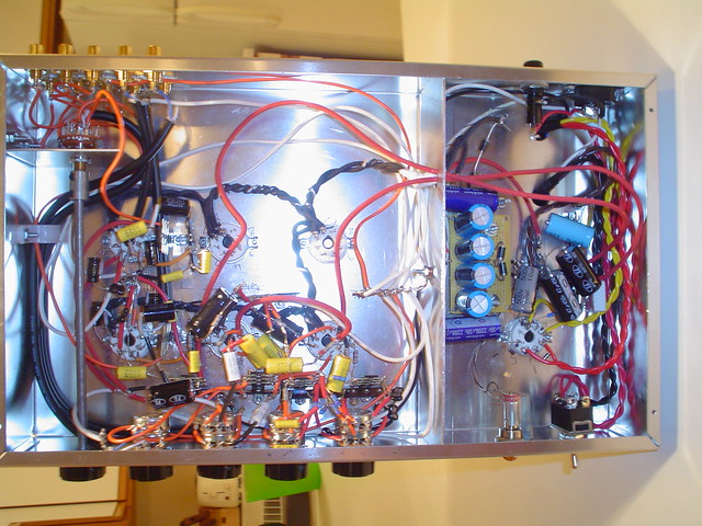
(1) I don't like the look of the heater windings in photo 04. Those LONG white (and orange) wires running in parallel with them seems like a hum recipe, unless they are unbalanced coax! Since they are hanging loose, try pushing them all to the top and strapping them into the chassis floor/wall corner angle. The golden rule is signal wires ALL at right angles to heater runs.
(2) The heater wire twisting is very uneven. I'd cut it out and start again with a smaller gauge insulator and tighten that down and straighten the runs.
(3) The long extension switch to the back of cabinet also looks like trouble. I see SOME coax running to the front knobs, but ideally you could simplify this spagetti immensely if you just ran coax back to front, then started manipulating it at the front.
(4) The whole front section should be boxed. You have a divider shield between the PS and the amp, but it looks like it does nothing. Better would have been a shield between the front volume/tone controls (including the caps) and the tube sockets and heaters.
(5) You can have longer runs with the power tube signals. That would allow you to move all the caps and crap back forward into the front, away from the heaters.
(6) I'm not seeing the physical star-ground I'd like in the center-front of amp. All those long white and orange leads look like trouble no matter where they are run.
(7) Did you rectify the heater voltages? You should. I know people say that is a waste of time, but I don't think so. It would eliminate a whole pile of headaches here in regard to the heater-lines, and it might be the easiest solution to your spagetti job.
(8) Did you float the heater-lines? They should/could float at about 50-100 volts above ground. Try removing the center-tap from the heater supply, if you've grounded it. That might make a whole lot of hum disappear.
(9) Simple test: Unscrew the mounts holding the transformer. Turn on the amp. Turn the transformer slowly to minimize hum. If it improves, rebolt it to the new orientation.
(10) Shorten leads DRASTICALLY to first stage and shield them. It should be a shielded lead going directly from RCA in to first stage, no longer than an inch or two, and shielded by coax. All volume knobs and other needless crap should be in the next stages or eliminated.
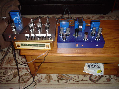
I can't see a picture of the underside of your power-amp, but it looks like an ST-70 clone, and I'm guessing its far worse than what you have shown with the silver chassis.
Also, do you seriously want your output transformer next to your preamp stage?
How about at least a foot of space here?
Is there a choke in the power amp PS? There better be. If its < 5 H double it.
You could probably re-mount the power cap and rectifier tube further from the amps (centered better).
Rotating the power transformer so its sitting on its capplate might do wonders for the power section.
(1) I don't like the look of the heater windings in photo 04. Those LONG white (and orange) wires running in parallel with them seems like a hum recipe, unless they are unbalanced coax! Since they are hanging loose, try pushing them all to the top and strapping them into the chassis floor/wall corner angle. The golden rule is signal wires ALL at right angles to heater runs.
(2) The heater wire twisting is very uneven. I'd cut it out and start again with a smaller gauge insulator and tighten that down and straighten the runs.
(3) The long extension switch to the back of cabinet also looks like trouble. I see SOME coax running to the front knobs, but ideally you could simplify this spagetti immensely if you just ran coax back to front, then started manipulating it at the front.
(4) The whole front section should be boxed. You have a divider shield between the PS and the amp, but it looks like it does nothing. Better would have been a shield between the front volume/tone controls (including the caps) and the tube sockets and heaters.
(5) You can have longer runs with the power tube signals. That would allow you to move all the caps and crap back forward into the front, away from the heaters.
(6) I'm not seeing the physical star-ground I'd like in the center-front of amp. All those long white and orange leads look like trouble no matter where they are run.
(7) Did you rectify the heater voltages? You should. I know people say that is a waste of time, but I don't think so. It would eliminate a whole pile of headaches here in regard to the heater-lines, and it might be the easiest solution to your spagetti job.
(8) Did you float the heater-lines? They should/could float at about 50-100 volts above ground. Try removing the center-tap from the heater supply, if you've grounded it. That might make a whole lot of hum disappear.
(9) Simple test: Unscrew the mounts holding the transformer. Turn on the amp. Turn the transformer slowly to minimize hum. If it improves, rebolt it to the new orientation.
(10) Shorten leads DRASTICALLY to first stage and shield them. It should be a shielded lead going directly from RCA in to first stage, no longer than an inch or two, and shielded by coax. All volume knobs and other needless crap should be in the next stages or eliminated.
I can't see a picture of the underside of your power-amp, but it looks like an ST-70 clone, and I'm guessing its far worse than what you have shown with the silver chassis.
Also, do you seriously want your output transformer next to your preamp stage?
How about at least a foot of space here?
Is there a choke in the power amp PS? There better be. If its < 5 H double it.
You could probably re-mount the power cap and rectifier tube further from the amps (centered better).
Rotating the power transformer so its sitting on its capplate might do wonders for the power section.
Last edited:
heater wiring - the Good the Bad and the Ugly
looking over photos of DIY projects on the net, and hearing the many stories about hum, makes me want to offer some observations that might help amateur builders.
Understanding the problem of tube heaters and hum is the first step toward ensuring your wiring job will be good enough to give happy results (no hum).
(1) The heater supply is usually A.C. (alternating current), a 50 or 60 cycle voltage taken from a winding off of the power-supply transformer. As such, it is usually more or less a sine-curve (but often with additional components, harmonics), but can actually appear as gross as a sawtooth depending upon the quality of your line voltage.
(2) For hi-fi and musical applications, the heater lines unfortunately provide a way in for noise from the mains (random hash, transients), and also radio frequency noise (RF), because the wires can also act as antennae, picking up noise from nearby motors and other equipment.
(3) So even if you don't convert your Alternating Current (A.C.) power to Direct Current (D.C.), you will still want to have some filtering and protection from line and radio noise.
(4) Also, if you don't convert to D.C., the 60 cycle A.C. hum will leak into other nearby circuits through the electromagnetic field coming off the heater wires, unless you take some precautions.
(5) As well, noise from other parts of the amp (the High Voltage HV supply, the screen supply and bias supplies) can also pick up and inject noise back into the heater lines.
(6) Many people don't bother to convert A.C. to D.C. for the heaters, and so other methods must be applied to minimize hum and noise. This is sometimes a cheaper solution.
In any case, hum and noise remains a problem with amplifier circuits, so basic strategies should be used.
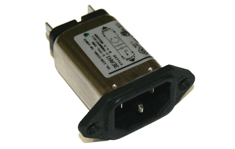
Regardless of whether or not you convert A.C. to D.C. (removing most of the hum), the Mains coming into the amp should be filtered and/or isolated from line noise. This can be done with a basic capacitor network on the lines.
It can be built into the line plug:
-----------------------------------------------------
looking over photos of DIY projects on the net, and hearing the many stories about hum, makes me want to offer some observations that might help amateur builders.
Understanding the problem of tube heaters and hum is the first step toward ensuring your wiring job will be good enough to give happy results (no hum).
(1) The heater supply is usually A.C. (alternating current), a 50 or 60 cycle voltage taken from a winding off of the power-supply transformer. As such, it is usually more or less a sine-curve (but often with additional components, harmonics), but can actually appear as gross as a sawtooth depending upon the quality of your line voltage.
(2) For hi-fi and musical applications, the heater lines unfortunately provide a way in for noise from the mains (random hash, transients), and also radio frequency noise (RF), because the wires can also act as antennae, picking up noise from nearby motors and other equipment.
(3) So even if you don't convert your Alternating Current (A.C.) power to Direct Current (D.C.), you will still want to have some filtering and protection from line and radio noise.
(4) Also, if you don't convert to D.C., the 60 cycle A.C. hum will leak into other nearby circuits through the electromagnetic field coming off the heater wires, unless you take some precautions.
(5) As well, noise from other parts of the amp (the High Voltage HV supply, the screen supply and bias supplies) can also pick up and inject noise back into the heater lines.
(6) Many people don't bother to convert A.C. to D.C. for the heaters, and so other methods must be applied to minimize hum and noise. This is sometimes a cheaper solution.
In any case, hum and noise remains a problem with amplifier circuits, so basic strategies should be used.
Regardless of whether or not you convert A.C. to D.C. (removing most of the hum), the Mains coming into the amp should be filtered and/or isolated from line noise. This can be done with a basic capacitor network on the lines.
It can be built into the line plug:
-----------------------------------------------------
Next, comes the layout of the heater wiring itself.
(1) The A.C. supply wires are twisted together, to collapse and minimize the field around each. At the same time as current flows in one direction on one line, it is returning in the opposite direction on the other line, and the two fields interact and cancel each other out.
(2) But there is ANOTHER reason why the wires are twisted together, which is often forgotten or neglected: It also stiffens the delivery system and minimizes movement of the wires. What movement? Any motion in a wire carrying current, or in a magnetic field generates a signal, or creates a coupling field. The motion can be very small, almost invisible, as in a guitar or violin string. It will still be very significant here.

The practice of twisting wires is also done to greatly stiffen them, minimizing motion and coupling fields.
(3) This is also the reason why SOLID wire (such as 18 to 14 gauge) should be used for heater leads. In fact, any and all electrical activity has an impact on all metal in the area, and in case you haven't guessed it, will also cause physical forces of motion on the wires. Here we DON'T want flexibility, but rather stiffness.
If you doubt this, or think it is insignificant,
try loosening the bracing bolts on your power transformer,
and listening to the horrible vibrating rattles as the E-I sections bounce around.
(1) The A.C. supply wires are twisted together, to collapse and minimize the field around each. At the same time as current flows in one direction on one line, it is returning in the opposite direction on the other line, and the two fields interact and cancel each other out.
(2) But there is ANOTHER reason why the wires are twisted together, which is often forgotten or neglected: It also stiffens the delivery system and minimizes movement of the wires. What movement? Any motion in a wire carrying current, or in a magnetic field generates a signal, or creates a coupling field. The motion can be very small, almost invisible, as in a guitar or violin string. It will still be very significant here.
The practice of twisting wires is also done to greatly stiffen them, minimizing motion and coupling fields.
(3) This is also the reason why SOLID wire (such as 18 to 14 gauge) should be used for heater leads. In fact, any and all electrical activity has an impact on all metal in the area, and in case you haven't guessed it, will also cause physical forces of motion on the wires. Here we DON'T want flexibility, but rather stiffness.
If you doubt this, or think it is insignificant,
try loosening the bracing bolts on your power transformer,
and listening to the horrible vibrating rattles as the E-I sections bounce around.
Last edited:
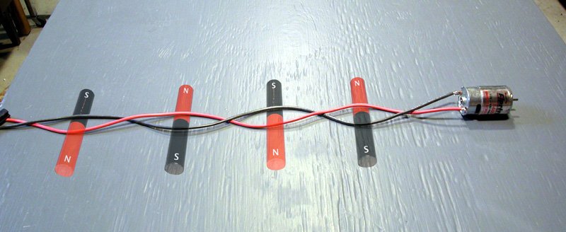
(4) Getting back to the theory behind twisting the wires, We want to recognise also that the number of twists is also strongly related to the DISTANCE to the next object that might pick up the signal, by the Inverse Square Law:
On the other hand, if you twist the wires too tight, you can also short them or break them or weaken them to the point where they generate resistance and heat unevenly, so there is a limit to how much you can coil / twist the wires before you risk damaging them.
Thus we want as many twists as possible (per inch), to minimize the proximity effect to other nearby objects."The circuit is essentially a coreless electromagnet with only a single turn of wire. By twisting the wires, we produce many small electromagnets, instead of one large one. Furthermore, these many small magnets are pointing in alternating directions. If we were very close to one of these magnets, we could still detect it, but once we are a small distance away, the adjacent opposing magnets will cancel it out (figure 3)."
On the other hand, if you twist the wires too tight, you can also short them or break them or weaken them to the point where they generate resistance and heat unevenly, so there is a limit to how much you can coil / twist the wires before you risk damaging them.
Now we are ready to understand why many seemingly good efforts at heater-wire dressing fail.
The hum is directly related to distance:
(1) The most sensitive components are the ones closest to the heater wire. That would be the area right around the socket! This is typically where the twisting-dressing technique is done the most poorly and sloppily!
(2) Wires at a right-angle to the heater-wire are the least sensitive to hum. Often wires and components are laid out badly in regard to this obvious issue: orientation.
(3) Other components may or may not be more or less sensitive to heater hum depending on orientation. THERE ARE NO general rules for this. For instance, its a bit tricky to orient a coil (or a cap!) for minimum hum, because it has a 3-dimensional field! Some components will be sensitive in ANY orientation, and must be shielded.
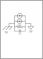
Ok Guys, so its been a while. So to answer some of your questions. No that amp in the older picture is not a st70 clone. I wish it was maybe I’ll build it when I master this preamp. That amp was modified after the picture to the Dynaco a410 schematic and that’s what you see in my new pics. So for the other news yes I did get most of the hum eliminated but there is still a little there. The long white and orange wires are ground wires, I used the extension shaft so my signal wires don’t have to travel long and pick up more stuff and there is a shielded 2 wire that the drain wire is grounded at one end for the longer signal runs. The divider keeps all the ac to one side. Yes the heaters are dc driven but I need a better filter due to a volt of ripple. The star ground is mounted on the divider but insulated from the chassis then I did do the 10 ohm .1 uf and 2 diodes ground connection. The heater lines are not floating about ground yet.
So a little explaining about the pictures of the scope. All pictures are taken with the probe at 1x and the voltage at 10mv. 005 | Flickr - Photo Sharing!
I clipped the probe to the output of one channels hmm ok looks like a lot of random noise from the room so then I flipped on the preamp and it looks the same then I turned on the amp and it still looked the same.
007 | Flickr - Photo Sharing! Note this one the scope is set to 20mv
When I hooked up the ground that Is attached to the probe to the ground case the scope looking noise goes down but the hum is still there as seen above. When the probe is attached to the ground of the case and without the probe ground attached the signal looks like all the other screen pics. I did flip the switch from dc to ac and the screen looked the same. You can’t see it in the pics but the trace is just a blur.
001 | Flickr - Photo Sharing! amp
002 | Flickr - Photo Sharing!
Guess I'll keep hacking away at this. Thanks guys.
Mike
If you find the root cause of your hum problem, be so kind and post it. I'm aftaid I have quite exact the same sympthoms with my EL84 SE.
When turning the volume pot louder the hum also gets louder, if the pot is maxed the hum dissapears completely.
The hum is also absent, when the I use the headphone out (it has a volume pot) on my CD player instead of line out and byass the amplifiers volume pot.
My signal ground is connected straight to power ground, safety earth connects only to chasis.
OK, lets see.....
now you want to hook up 1 preamp to two or one amplifiers that are DIY right?
an impedance mismatch is happening to you. at the output of the preamp to the input of the amps.
I assuming that you want the independent input controls of the amp.
this goes back to the arbitrary 100k in DIY amp designs people. 100k is arbitrary and those designs require tweaking.
and is around the lowest possible input impedance that a tube amp on the input can run.
if you were just running one amplifier, you could just increase the potentiometer on the one amp from 100k to 500K then the effective coupling impedance is 250K (this is a better loading by far) now the second amp in parallel: with its 100k substituted with a 500k would be effective loading impedence of 166K ( a little low, but reasonable). Now insert a 220K resistor between the connection of the potentiometer on the amplifier(s) and ground. you'll notice that increasing the resistance path from input grid to ground makes your problems go away.
have a nice day...
If the problem is capacitive coupling then increasing circuit impedances will make it worse.
dc coupling works, you just need to look at whats going on.
Btw, the preamp is already ac coupled.
just looking at both amps, if the 100k pot on the one amp is changed to 1M and the 470K on the other amp changed to 1M.
the the reflective Z is 250K. if you have noise in one to another its because one amp is imposing voltage on another. this can be combated by increasing the grid snubber resistor to compensate.
unless you want to give up on the dc coupling, then you can ac couple one or the other or both with a simple 1Uf 250V cap. But the need of impedance balancing is still needed.
What has DC coupling got to do with it? I have no idea what you are talking about. Please explain how raising circuit impedances will reduce hum (not noise) wnen there may be evidence that some of the hum is being caused by capacitive coupling to a high impedance point. When the slider hits max the hum disappears, because at that point the circuit node is connected directly to the low impedance output of the source.
It does not look like the power supply is complete, the problem is all in the power supply as it is producing ripple voltage.
Looking at the picture of the amp, wire a 4700 ohm 2 watt resistor between the plus side of the two caps.
Wire that resistor, one end to the plus side of the one cap and the other end of the resistor to the plus side of the other cap.
That should reduce it, if it does, then we can go further.
Looking at the picture of the amp, wire a 4700 ohm 2 watt resistor between the plus side of the two caps.
Wire that resistor, one end to the plus side of the one cap and the other end of the resistor to the plus side of the other cap.
That should reduce it, if it does, then we can go further.
Last edited:
If you find the root cause of your hum problem, be so kind and post it. I'm aftaid I have quite exact the same sympthoms with my EL84 SE.
.
My hum problem was an issue of a wiring mistake on my DC supply for my preamp tubes and poor construction in the amp. After fixing the heater supply in the preamp and rebuilding/new layout with the amp I have little to none hum. Thanks for asking.
Mike
- Status
- This old topic is closed. If you want to reopen this topic, contact a moderator using the "Report Post" button.
- Home
- Amplifiers
- Tubes / Valves
- Amp hum with Preamp off