Hi Bensen,
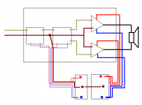
It looks like amp 1 & 2 have a combined ground on each.
I wonder if this is making your problem worse. If it is I have no solution.
But keep trying the options and post us the successes as well as failures. Some day we might all be using mixed, dirty and clean combined grounds on a 2channel amp.
It looks like amp 1 & 2 have a combined ground on each.
I wonder if this is making your problem worse. If it is I have no solution.
But keep trying the options and post us the successes as well as failures. Some day we might all be using mixed, dirty and clean combined grounds on a 2channel amp.
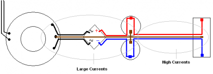
Minimize the current loops.
Not just on the long wires section, but right
at the terimals also, as on the attachment.
Every pair of wire which carries the same current,
should be as close as possible to each other.
Specially when it carries large currents, impulses, or
when its a sensitive loop, like signal, input stage, etc.
Not just on the long wires section, but right
at the terimals also, as on the attachment.
Every pair of wire which carries the same current,
should be as close as possible to each other.
Specially when it carries large currents, impulses, or
when its a sensitive loop, like signal, input stage, etc.
Attachments
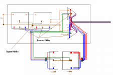
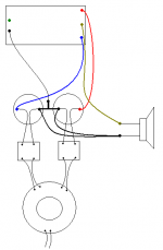
An other possible layout for you Bensen:
Large currents separate on the right side (red + blue + purple),
nothing GND wire (unnecessary cause of bridge mode).
Signal and small power currents on the left side.
There is 3 separate GND, every one routed to the main PS GND starpoint.
- signal GND just for the signal points
- power GND for the 1st two stages
- power GND for the amp
But all this 3 wires are going close to eachother to the main GND.
I hope its clear...
Attachments
For future designs why not just put the power supply caps on the amplifier board. Layed out correctly it works great, and simplifies wiring. You connect the transformers three primary wires, audio in, and speakers and your all set. I'm researching this but if layed out correctly you may even be able to eliminate the L||R output.
> IF the noise is due to charging pulses, the following may help to reduce it:
> Connect a 103 ceramic cap across the diode for each arm of the bridge rectifier.
And why would this help ?
> With your second proposal, I will have groundloops.
> Because each power ground and signal ground are connected with eachother on each PCB.
Aham, I understand, then you cant separate the signalGNDs from the power GNDs.
Anyway the base concept remains the same, collect all the GND points to a starpoint
and route it to the main PS GND.
Hi Bensen,
Re layout in post25; just as you said, the signal ground from output board to signal ground needs to be omitted because you have a combined ground on the output board.
The other signal grounds (three from input and two low level stages) come together at the signal ground. The layout shows this signal ground running to the short ground leg feeding the 15V supply. Try this but also try connecting Signal-GNDs direct to Power-GNDs. As a third alternative try connecting Signal-GNDs via 10r to Power-GNDs.
Finally there are too many power grounds running to the output board; the thick green lines should go from 48V ground to Power-GNDs. Then the choice is take it from the PSU common or take the thick green from the short link running to the 15V PSU.
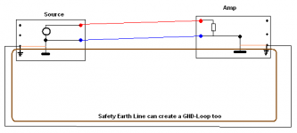
Re post26 earthing layout; there are safety grounds connected to the mains earthing system. These MUST be connected as shown.
There are also connections inside the gear from safety ground to either signal or power ground. These must be broken and the signal/power grounds left floating with respect to the chassis/safety ground. Now there is no hum/earth loop. This is where you can now fit the disconnecting network using that range of components including a ground lift switch but this lift switch must only be closed on ONE component. Experiment to find which component or none gives the quietest result.
Re layout in post25; just as you said, the signal ground from output board to signal ground needs to be omitted because you have a combined ground on the output board.
The other signal grounds (three from input and two low level stages) come together at the signal ground. The layout shows this signal ground running to the short ground leg feeding the 15V supply. Try this but also try connecting Signal-GNDs direct to Power-GNDs. As a third alternative try connecting Signal-GNDs via 10r to Power-GNDs.
Finally there are too many power grounds running to the output board; the thick green lines should go from 48V ground to Power-GNDs. Then the choice is take it from the PSU common or take the thick green from the short link running to the 15V PSU.
Re post26 earthing layout; there are safety grounds connected to the mains earthing system. These MUST be connected as shown.
There are also connections inside the gear from safety ground to either signal or power ground. These must be broken and the signal/power grounds left floating with respect to the chassis/safety ground. Now there is no hum/earth loop. This is where you can now fit the disconnecting network using that range of components including a ground lift switch but this lift switch must only be closed on ONE component. Experiment to find which component or none gives the quietest result.
Cortez said:What about this one ?
The point: the high current GND wire from the speaker goes
directly to the main filter caps as near to their legs as possible.
And the signal GND goes to the wire that connects to two caps.
Yes Cortez,
I do that always in my amps, except for this one, this is a bridged amp.
Greetz
- Status
- This old topic is closed. If you want to reopen this topic, contact a moderator using the "Report Post" button.
- Home
- Amplifiers
- Solid State
- amp grounding schemes