Hi moppy,
just what I've expected - now you have two secondarys 0-15V and can proceed as you intended.
cheers
A.
Alright. Thanks.
By the way, I got a new problem. Before that I am using a laptop psu, I have set it to 10v. After that I retest again (after a week) with the same laptop psu, the led is blinking, what does it means? I measure the power before plug in was 19.x volts and when I plug in to the boards, the reading is jumping up and down. It won't stable at 19.x volts.
Last edited:
I saw 2 wires joined together. Here what I do. I use meter to check the continunity test. Each blue wire only beep with 1 black wire. I think there's no shorting at all. Therefore, now can I use this for my power supply?
Zen Mod, what do you think? I guess this is easier for me to take every parts out from the pcb and reconnect it with wire.
you did what's shown on pictures - disconnected center tap connection , so now you have two independent windings ?
you did what's shown on pictures - disconnected center tap connection , so now you have two independent windings ?
Yes but now new problem.
I don't hv the pcb diagram. I bought this in ebay.
Any idea how?
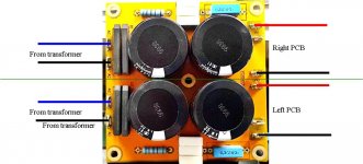
considering that entire upper copper plane is GND , you can't easily isolate upper and lower rectifiers and caps
now - desolder everything from pcb , and connect as per tutorial I posted
or buy new PSU pcbs , each made for simple rail
whatever it is , it's easy peasy ........ problem is in plateau of knowledge
I can't help more , at least not before you decide what is next step
Okyou would have to cut the ground plane on the top side along the green line and then I'd flip the lower bridges and big caps 180° to make one side a mirror.
Ok. I will have a looked and double check it.considering that entire upper copper plane is GND , you can't easily isolate upper and lower rectifiers and caps
now - desolder everything from pcb , and connect as per tutorial I posted
or buy new PSU pcbs , each made for simple rail
whatever it is , it's easy peasy ........ problem is in plateau of knowledge
I can't help more , at least not before you decide what is next step
24V Power Jack from MPJ wiring question
Could someone help with a power jack wiring question?
I am trying to wire my new 24V power supplies I got from Marlin P Jones.
However, the connectors are 4 pin and the jacks are different. There are 4 posts on the jack and 2 side posts that appear to be ground?
The 19V power supplies had a simple power and ground like in the ACA build guide.
Do I divide the voltage wire into 4 parts and the ground into 2 parts?
If not, what should I do? Thanks.
Ok. I've narrowed it down to pins 1 and 2 (closest to lock/bump and furthest apart from each other) are the VIN+ and pins 3 and 4 are the ground. But I still don't understand how the split works. Should I run a separate extra wire from the PCB voltage and attach to 1 and 2? And then the same for ground?
I really need some help, please. The specs for this jack say max 48V across all pins. So i attached the jack (not connected to the pcb) to the power supply to read the power output same as the build guide states to do with the 19V supply and jack (which worked fine). But when I touched the sleeve as the ground and any of the 4 pins wth the DMM I got sparks. I could not read the voltage this way.
This means a short, right? Do the four jack pins need to be jumpered (soldered) together to get the voltage? Or am I nowhere near doing this right?
This means a short, right? Do the four jack pins need to be jumpered (soldered) together to get the voltage? Or am I nowhere near doing this right?
only cooler with speakers and some Hendrix
dummy load is useful if you have something to measure with ;
have you signal generator and scope ?
naah ...... just connect source and some cheap speaker and blast!
there even can't be DC on output , unless you reeeeeeealy ooked up something

dummy load is useful if you have something to measure with ;
have you signal generator and scope ?
naah ...... just connect source and some cheap speaker and blast!
there even can't be DC on output , unless you reeeeeeealy ooked up something
only cooler with speakers and some Hendrix
dummy load is useful if you have something to measure with ;
have you signal generator and scope ?
naah ...... just connect source and some cheap speaker and blast!
there even can't be DC on output , unless you reeeeeeealy ooked up something
I don't have a signal generator ... well just get some cheap speaker and try it on tomorrow.
Download REW and it has signal generator for your sound interface.
Or use Audacity to generate a tone and play it.
Ok, will do.
Ok, connected everything and play some music. So far it played. The heatsink is hot but not so hot. I can hold it at least more than a minute. At the moment using laptop power supply. After run in a while I will replace with a 200VA toroidal transformer.
Thank you for diyaudio members who contribute their precious advise, especially Attila, Zen Mod and e_fortier.
Thank you for diyaudio members who contribute their precious advise, especially Attila, Zen Mod and e_fortier.
- Home
- Amplifiers
- Pass Labs
- Amp Camp Amp - ACA