I'm still trying to get a feel for the Mu Follower. In the ACA, is the value of R7 a major factor in the bias? If one wanted higher bias, what are the best options?
Can you lower the value of R7?
Would a Darlington at Q3 work well (to get a Vbe of 1.3 instead of .65)?
I used the addition of R15 in my build of the ACA, but would that type of solution work for any bias desired?
I'm also trying to understand how the J2 CS works, and I'm having a hard time drawing analogies to the ACA when it comes to the opto-isolator. Is the opto-isolator forcing a Vbe of 1.4V to get the 1.7A bias?
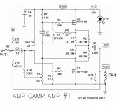
Operating current is determined by R1R2R3R4, and has nothing to do with the R7.
#1542, I use a 1 ohm, so current is 0.63 amps.
Q3eb=0.63V。
I have a bad understanding of the Mu Follower.Operating current is determined by R1R2R3R4, and has nothing to do with the R7.
#1542, I use a 1 ohm, so current is 0.63 amps.
Q3eb=0.63V。
What is the purpose of R7?
How does R15 increase the Bias with regard to the Vbe?
I have a bad understanding of the Mu Follower.
What is the purpose of R7?
How does R15 increase the Bias with regard to the Vbe?
R7 designed to provide Q2 bias, but bias voltage controlled by Q3.
Q3 control voltage to the voltage supplied by the current R1R2R3R4 over about 0.65V bias voltage of Q2.
R15 supplement aimed at each end of the R1R2R3R4 voltage R8R15 voltage divider. Voltage voltage of Q3 is still 0.65V,
R1~R4 voltage will be higher,
A better approach is to reduce the resistance of R1~R4.
As regards the actual total resistance up to R=0.65/I to reach.
Increase of R15 the right resistor is:
I (after)/I (ago) = (R8+R15)/R15
I hope you can understand, my English is very poor.
This is the result of machine translation.
Just be aware that you could damage some FETs if you drive the input with too much voltage like from a tube preamp. Keep the input under something like 10V peak to peak or be prepared to replace some parts.
Is it possible to add some zener protections diodes to avoid this?
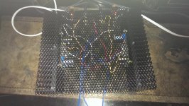
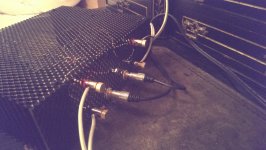
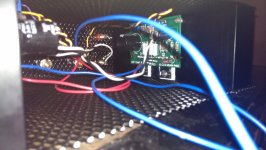
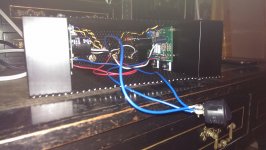
My ACA minus a finished chassis.
learnt loads doing it - still yet to do the mod with the resistor.
The hardest part was soldiering the plugs.
the worst part was drilling and tapping all the holes.
learnt loads doing it - still yet to do the mod with the resistor.
The hardest part was soldiering the plugs.
the worst part was drilling and tapping all the holes.
Attachments
install LTSpice and run this
I've never tried Spice, but I'm game.
On downloading, the program asks for SS library. Do you have the SemiSouth.lib for spice? I could not find it on google.
Wonderful!
Listen to it for an hour or so and then do the mod with the resistor -- it sets the operating point where it is supposed to be.
The mod is wonderful. Been listening for two days and they sound much better. I was just a bit short on gain but have a full presentation now with only a direct feed from the DAC. Thanks for the tip.
Last edited:
Wonderful!
Listen to it for an hour or so and then do the mod with the resistor -- it sets the operating point where it is supposed to be.
Cheers 6L6. I opted for a single power input hence the snakes wedding in wires. I am yet to find a sensible way of routing them all in one chassis.
I've still got alot to learn but its a start. I have researched what all the components do individually but what they do all connected to each other is the next step.
What do you mean by operating point?
Other terms I am yet to understand fully:
Bias
Inductance
Power rail
Feedback
Thanks to one of the articles on this forum I now undertsand 'gain' and 'attenuation' but every explanation I find of the above just introduces more terms...
Would it be possible to convert ACA to current feedback with this mod?
That looks like it would work. Find values for the resistors by experimentation.
Is it possible to add some zener protections diodes to avoid this?
Zener protection is possible. There is a schematic in the thread I posted a link to above.
A better approach is to reduce the resistance of R1~R4.
The R1-R2 to R3-R4 ratio, as well as their absolute value, (and the transconductance of Q2) determine how Q2 assists Q1 in supplying current to the load. Those resistors also influence the open loop gain and the distortion profile. IMHO the R15 mod is the best way to go, but seemingly little changes to the ACA change many other things.
........I've still got alot to learn but its a start. I have researched what all the components do individually but what they do all connected to each other is the next step.....
One of the best sources for all things audio. Check out the full site index.
Amplifier Basics.
Bookmarked thank you. I can tick off 'feedback' and 'gain' on the list. I've read a lot that feedback is not necessarily a good thing, given the description in that webpage I can't see why it would be bad. am I right in saying it cancels out errors induced by the amplification process?
The mod is wonderful. Been listening for two days and they sound much better. I was just a bit short on gain but have a full presentation now with only a direct feed from the DAC. Thanks for the tip.
Agreed ! Listening to the mod for 3 weeks and the bass which was a bit low with my big woofers seems to have improved also.
NYCOne
you don't need that for that file - just delete line with scissors
it's orphaned line from something previous
later , if you continue to play with LTS , just ask for SS
First time with Spice - AWESOME.
You engineering types need to get more of us into it.
It's a lot like losing my virginity all over again. I'm sure I'll have questions, but it's a lot of fun!
Last edited:
The cabinet looks great. Where can you buy them?This amp with that bias mod is really loud. I found that I don't need more power, and I use a B1 as a "pre". However, you can hear the the amp has a bit higher THD compare to begged FW amps, especially on higher volumes. If you listen to simple enough music, you will newer notice, but I am a huge Steve Vai fan. Don't get me wrong this is a really nice sounding amp, I put it way above F5 for example. And the bass, it will surprise you... But I have a better PSU, can't say about ones from that kits.
Some more pictures of finished amp:


- Home
- Amplifiers
- Pass Labs
- Amp Camp Amp - ACA