Beefy ps for ACA
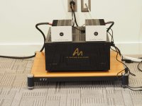
I finally finished my linear ps for my ACA's. I apologize for the poor pictures but my camera broke; so we get iphone pictures. My goal was to build it with the left over parts I had on hand. A second goal was to see if I could learn anything before I build the bigger ps for the Aleph J that I already started.
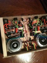
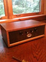
I used CLC with 60k uF before the choke, and 60k uF after. The last 10,000uF is connected to the amp end of the cable. I used a cheaper choke with higher resistance, but if I had to do over, I would use the lower resistance chokes from Madisound like I am on my Aleph J. The capacitors and LED's are held in with hot glue (my friend). For sheathing I used bright colored paracord and pulled out the middle. I do not have a shop, so I bought an NOS radio case from Surplus of Nebraska. It required a “drawer” insert, sliding in from the front, so I had a friend with a table saw cut up the drawer with scrap wood. For the connectors I heard that Buzzforb was using Nuetrik Speakon and I tried them. They are great and low cost. I will use them everywhere I can.
My first round using my Antek 50VA, 15V secondary only produced 17.8VDC. So I broke down and had to buy two Antec 100VA, 15V which gives me about 19VDC. My mains voltage varies, so at night I get 19.2VDC. At night it sounds a little better. I realized I did not need a CL60 on the input and took them out. I do not need the bridge rectifier for the chassis ground. A lone CL60 there will do. After they warmed up I checked the ACA adjustment and it still said 10.00VDC, so I left good enough alone. The first thing I noticed over the bricks was that I could no longer hear the slight buzz and hiss when I put my ear to the speaker. It is dead quiet now. Overall the change in sound is subtle. In the evening I can hear a little more low level detail. I am very happy. On one CD that I have heard over 50 times, I suddenly could make out a couple of words the female singer was singing. Is it worth the trouble for most people? Probably not. Should a person first build the ACA using the bricks? Definitely!
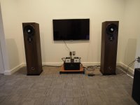
As I said in a post several months ago, these are driving a pair of Madisound speaker kits, ZRT. The 7” Scan-spec driver is only 87db, yet these are loud enough for me 98% of the time in my medium small living room. The sound is so sweet. The main reason I am building an Aleph J is for the other 2% of the time (and I like to build a good amp).
I finally finished my linear ps for my ACA's. I apologize for the poor pictures but my camera broke; so we get iphone pictures. My goal was to build it with the left over parts I had on hand. A second goal was to see if I could learn anything before I build the bigger ps for the Aleph J that I already started.
I used CLC with 60k uF before the choke, and 60k uF after. The last 10,000uF is connected to the amp end of the cable. I used a cheaper choke with higher resistance, but if I had to do over, I would use the lower resistance chokes from Madisound like I am on my Aleph J. The capacitors and LED's are held in with hot glue (my friend). For sheathing I used bright colored paracord and pulled out the middle. I do not have a shop, so I bought an NOS radio case from Surplus of Nebraska. It required a “drawer” insert, sliding in from the front, so I had a friend with a table saw cut up the drawer with scrap wood. For the connectors I heard that Buzzforb was using Nuetrik Speakon and I tried them. They are great and low cost. I will use them everywhere I can.
My first round using my Antek 50VA, 15V secondary only produced 17.8VDC. So I broke down and had to buy two Antec 100VA, 15V which gives me about 19VDC. My mains voltage varies, so at night I get 19.2VDC. At night it sounds a little better. I realized I did not need a CL60 on the input and took them out. I do not need the bridge rectifier for the chassis ground. A lone CL60 there will do. After they warmed up I checked the ACA adjustment and it still said 10.00VDC, so I left good enough alone. The first thing I noticed over the bricks was that I could no longer hear the slight buzz and hiss when I put my ear to the speaker. It is dead quiet now. Overall the change in sound is subtle. In the evening I can hear a little more low level detail. I am very happy. On one CD that I have heard over 50 times, I suddenly could make out a couple of words the female singer was singing. Is it worth the trouble for most people? Probably not. Should a person first build the ACA using the bricks? Definitely!
As I said in a post several months ago, these are driving a pair of Madisound speaker kits, ZRT. The 7” Scan-spec driver is only 87db, yet these are loud enough for me 98% of the time in my medium small living room. The sound is so sweet. The main reason I am building an Aleph J is for the other 2% of the time (and I like to build a good amp).
Attachments
With that many uF's on the rail the turn off thump should be ruduced. Can you still hear it or see the woofers move?
There is no turn-off thump. If the thump is a problem for someone using the bricks, notice there is no thump when you unplug them from the AC outlet. The switch on the ACA disconnects the DC out, not the AC in. The thump was not a big problem to me with the bricks, but I usually left mine on or unplugged them if gone. Maybe someone could try an outlet that uses a light switch and see if turning off the switch has no thump. At the moment I am not sure if you would need to disconnect both the AC hot and neutral (ground) or just the AC hot to get rid of the thump.
Are you sure that you have your meter reading DC voltage, and you are on the center pin of Q1?
Newbie mistake for sure. I had another go at it, and I did indeed have the meter on resistance, not voltage.
Works fine now. That pot is fickle though, lots of up and down to get about 10.6v.
Wiring up the other side now.
ACA in action
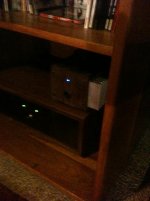
Finished my ACA monoblocks. Playing them now with a set of Zu Audio Essence speakers (newly upgraded main driver and crossover). Sound very nice, takes more power from the pre-amp than the 35 watt tube amp they are sitting on. They sound really good, the bass is improving slightly over the afternoon. They will end up on smaller speakers in a nearfield setup.
Thanks for the great amp/kit!
Attachments

Just finished my first one, and I can't seem to get the voltage between the center pin of Q1 and GND above 5.5v, even with the trim pot maxed out. Any ideas what could be wrong?
Do Q1 and Q2 get hot?
Is Q3 installed correctly with the flat side away from C2?
Did you verify by color code or resistance check the value of the resistors you installed? Did you observe the polarity of capacitors you installed?
Take voltage readings at each transistor pin as indicated in the diagram below.
Attachments
Last edited:
Heat sink chassis screw holes misaligned
DIY Audio - I'm working on the ACA kit that I recently received and just noticed that the screw holes on one of my heat sinks are off. Luckily, I haven't soldered anything to the heat sink yet. How do I get a replacement?
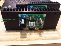
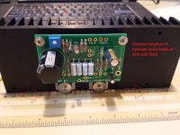
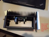
See attached photos - you'll see that the 'correct' heat sink, where the heat sink screw holes line up with the chassis, has chassis screw holes at ~2cm and 18cm; the one that is incorrect has chassis screw holes at ~3cm and 19cm. As a result, there's a gap that exists.
Please let me know asap how to get this corrected - thanks!
DIY Audio - I'm working on the ACA kit that I recently received and just noticed that the screw holes on one of my heat sinks are off. Luckily, I haven't soldered anything to the heat sink yet. How do I get a replacement?
See attached photos - you'll see that the 'correct' heat sink, where the heat sink screw holes line up with the chassis, has chassis screw holes at ~2cm and 18cm; the one that is incorrect has chassis screw holes at ~3cm and 19cm. As a result, there's a gap that exists.
Please let me know asap how to get this corrected - thanks!
Attachments
Question on orientation for optimal cooling...
I'm still in the process of building my ACAs (need to get resolution on my heatsink misalignment issue), but I have a question about orientation. Wouldn't it be best to align the PCB so that the mosfets are at the top side of the PCB, not below the PCB, for optimum cooling? (I'm talking about the kits where the PCB is mounted on the side of the chassis - I'm not asking if it's better to put the mosfets on the bottom or top of the chassis.) Would this make any difference, or am I making a big deal out of nothing?
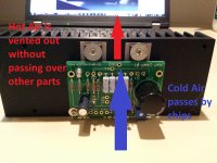
I was looking at the pictures of many others' work, and noticed that in every picture I saw, everyone put the mosfets at the bottom. Because heat rises, that means that every other part on the board gets the heat from the mosfets. My thinking is that if I put the mosfets at the top, the capacitors would get the cool air coming underneath and therefore operate at a lower temperature.
(My wife says that I'm anal about my stereo equipment - that's probably all this is. But I am interested in knowing what is optimal. (Another aside - my day job is in networking and I did have to work on an issue where capacitors were experiencing early life failure due to high temperatures.))
Thanks in advance!
I'm still in the process of building my ACAs (need to get resolution on my heatsink misalignment issue), but I have a question about orientation. Wouldn't it be best to align the PCB so that the mosfets are at the top side of the PCB, not below the PCB, for optimum cooling? (I'm talking about the kits where the PCB is mounted on the side of the chassis - I'm not asking if it's better to put the mosfets on the bottom or top of the chassis.) Would this make any difference, or am I making a big deal out of nothing?
I was looking at the pictures of many others' work, and noticed that in every picture I saw, everyone put the mosfets at the bottom. Because heat rises, that means that every other part on the board gets the heat from the mosfets. My thinking is that if I put the mosfets at the top, the capacitors would get the cool air coming underneath and therefore operate at a lower temperature.
(My wife says that I'm anal about my stereo equipment - that's probably all this is. But I am interested in knowing what is optimal. (Another aside - my day job is in networking and I did have to work on an issue where capacitors were experiencing early life failure due to high temperatures.))
Thanks in advance!
Attachments
I've got one working perfectly and the other buzzes. The buzz gets progressively worse and is only present with the input plugged in. I've switched all external connections from one amp to the other, no change. Q1 and Q2 get warm but I wouldn't say even close to hot. Q3 flat is away from C2 and all resistor values are correct. Polarity of caps is correct.
C1 + = 10
C1 - = 0
Q1s = 0
Q1d = 10.1
Q1g = 4.5
Q2s = 10.7
Q2d = 19
Q2g = 15.3
C4+ = 19
C4- = 0
Q4d = 4.5
Q4g = 4
Q4s = 4.5
C3+= 19
C3-=4
Q3e=10.1
Q3b=10.7
Q3c=15.3
I've got C2 down so tight I can't get to connections without more disassembly.
Going to measure the other for reference.
Help?
Thanks
Aaron
I was looking at the pictures of many others' work, and noticed that in every picture I saw, everyone put the mosfets at the bottom. Because heat rises, that means that every other part on the board gets the heat from the mosfets. My thinking is that if I put the mosfets at the top, the capacitors would get the cool air coming underneath and therefore operate at a lower temperature.
Thanks in advance!
I am pretty sure the hot stuff is located low on the heat sink to maximize the cooling effect of the heat sink. While the heat sink prevents the MOSFET from frying, it really is designed to allow the MOSFET to operate at a temperature that puts the transistor to work in the best manner possible (gain and distortion). The heat sink works most efficiently if the heat is loaded down low, using the whole heat sink for cooling. Convection causing air movement on the fins works best if the fins are hotter on the bottom. That being said, I don't know how much less efficient the system would be if loaded the other way. Also, my ACA does not get overly hot.
DIY Audio - I'm working on the ACA kit that I recently received and just noticed that the screw holes on one of my heat sinks are off. Luckily, I haven't soldered anything to the heat sink yet. How do I get a replacement?
See attached photos - you'll see that the 'correct' heat sink, where the heat sink screw holes line up with the chassis, has chassis screw holes at ~2cm and 18cm; the one that is incorrect has chassis screw holes at ~3cm and 19cm. As a result, there's a gap that exists.
Please let me know asap how to get this corrected - thanks!
It's very easy to learn how to drill and tap holes. I understand you may not want to go down that road though
- Home
- Amplifiers
- Pass Labs
- Amp Camp Amp - ACA