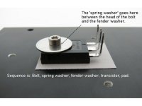
In case the bolt is not “perfectly” perpendicular to the area of the device, you will either end up with too little pressure, or you will put too much pressure on certain areas and could “crush” the surface. So you put a split washer to compensate for that, and also help to prevent the bolt from getting lose.
I prefer to have the split washer between the bolt and the flat washer. But that requires that the bolt’s head be wide enough to actually “grab” the split washer. If not, put the split washer between the flat washer and the device.
Hope this helps, others will have more insight.
I prefer to have the split washer between the bolt and the flat washer. But that requires that the bolt’s head be wide enough to actually “grab” the split washer. If not, put the split washer between the flat washer and the device.
Hope this helps, others will have more insight.
It was definitely the power supplies. I tried the 24 Volt TDK supply, and it’s dead quiet.
fine...problem solved
")
If not, put the split washer between the flat washer and the device.
Personally I would not do this as the large washer is there to spread the load over the device. I would do, device, then large washer, split washer (and if required) smaller flat washer, and then bolt.
Can you help me figure out the position of the lock and spring washers for the mounting of the big transistors to the heat sink? I understand the top bolt and washer will be used but they also mentioned a split washer and spring washer .??
Spring washer and split washer are the same thing, just different names.
It does not matter if you leave it out, but if you fit it it Must go between the bolt head and fender washer.
The spring washer is not shown in the build guide picture Step 14. But is referred to in the text as a lock washer (split/spring washer).
Alan
Attachments
Last edited:
Noise is back
The noise is back. When the TDK power supply was loose and not inside a chassis, it was silent at the speakers. Now that it is in a chassis, it makes the same noise that the 24 Volt laptop supplies did. This noise only happens when the amp signal inputs are connected to my DAC. If I put shorting plugs into the RCA jacks, it is silent again. Attaching the 19 Volt supplies that I use on my monoblock ACAs results in silence at the speakers whether or not the inputs are shorted or attached to the DAC.
This is driving me crazy. Why would the supply be quiet when it is loose, but be noisy when it is in a chassis? If you have any ideas, please let me know.
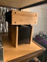
Attached is a photo of the amp on top of the supply. It's still noisy when placed away from the amp.
The noise is back. When the TDK power supply was loose and not inside a chassis, it was silent at the speakers. Now that it is in a chassis, it makes the same noise that the 24 Volt laptop supplies did. This noise only happens when the amp signal inputs are connected to my DAC. If I put shorting plugs into the RCA jacks, it is silent again. Attaching the 19 Volt supplies that I use on my monoblock ACAs results in silence at the speakers whether or not the inputs are shorted or attached to the DAC.
This is driving me crazy. Why would the supply be quiet when it is loose, but be noisy when it is in a chassis? If you have any ideas, please let me know.
Attached is a photo of the amp on top of the supply. It's still noisy when placed away from the amp.
Attachments
Just so I understand. You put supplies in a chassis and you have noise.
Do you extend the supply cord out of the chassis or is there another cord involved connected to a Jack on the chassis?
I found a work around. The chassis underneath the amp is a metal box that contains a TDK FAW24-4R2 supply. It is a 100 Watt supply with 24 Volt DC at 4.2 Amps. This supply has an input for line, neutral and ground. I detached the ground connection, and the noise disappeared. It was probably a ground loop problem of some sort. There was no noise at the speakers with the same supply and the ground wire attached if the rca inputs had shorting plugs in them.
. Thank goodness. I was getting ready to pull some hair out.Cool beans - sounds like you might be right about the loop !
I found a work around. The chassis underneath the amp is a metal box that contains a TDK FAW24-4R2 supply. It is a 100 Watt supply with 24 Volt DC at 4.2 Amps. This supply has an input for line, neutral and ground. I detached the ground connection, and the noise disappeared. It was probably a ground loop problem of some sort. There was no noise at the speakers with the same supply and the ground wire attached if the rca inputs had shorting plugs in them.
I have a similar problem; the SMPS has its own power line RFI connected filtering to the chassis of the building block and to the minus. There is 90V static on the house and if connected to the chassis, there to and on the ground plane of the ACA. . .
In my case, even with the SMPS lifted (wrapped in plastic) from the case, I still was 'connected' to the mains when I did not use the ground.
I asked the factory: can I take out one of the blue mains filter caps? No they said. (yes you can I think) and I plan I will use a real separate RFI filter somewhere else up the power line and open it up, take the cap out.
That static is just like old fashioned transformers in appliances in the audio circuit.
An Idea
 I have is connecting two SMPS bricks but withe the live and neutral connected differently on each - this would maybe cancel it out. Haven't done it yet, is now two ch - one SMPS.
If you remove the input source. Do you hear that noise? And what is the input source?
In my case, there is no noise with the input source disconnected. My source is a Musical Fidelity V90 DAC, which is powered by another SMPS.
In my case, there is no noise with the input source disconnected. My source is a Musical Fidelity V90 DAC, which is powered by another SMPS.
Reason I ask is.. my DAC is a mini-DSP. It is fed with a USB cable from my MAC mini. The output goes to my ACA amps. It is noiseless.
I can take the same cables from the mini dsp.. and plug them into an emotiva amp and it hears things like an arc in a light switch or a power saw turning on.
There is no earth connection on the Emotiva. And adding one does nothing to help or hurt.
Fortunately, We much prefer the ACA. With all of these observations though I have to wonder if perhaps it is the output impedance vs input impedance. Will dig in a little and see.
Good Day everyone!
Well I thought my ACA build was going swimmingly but unfortunately it is not cooperating. I went to bias it up and both boards are having issues. One board maxes out at 6v at one end of the pot, the other the pot does nothing. I'm hoping to get some help troubleshooting the board where the pot does nothing first and try to apply that knowledge to see if I can troubleshoot the other one on my own.
Prior to any assembly, I measured all resistor values and logged them, double checking values when stuffing the board.
I gave the boards a once over and I don't see any cold solder joints or solder bridges (even though I was a bit heavy handed with the solder I'll admit). If that's the verdict based on my testing results below then I'll do it again.
When I was trying to do some work on case with the boards populated I did knock over C4 over on about a 45 degree on both boards. I straightened them back up (hole spacing wouldn't let me mount flush so there was a little lead to play with). I don't believe I damaged the caps, but I thought I would mention it.
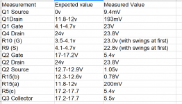
In the build guide there is a troubleshooting photo that shows expected values in key places when the board is powered up and allowed to stabilize at operating temperature. Here are the results:
Measurement Expected value Measured Value
Q1 Source 0v 9.4mV
Q1Drain 11.8-12v 193mV
Q1 Gate 4.1-4.7v 23V
Q4 Drain 24v 23.8V
R10 (G) 3.5-4.1v 23.0v (with swings at first)
R9 (S) 4.1-4.7v 22.8v (with swings at first)
Q2 Gate 17-17.2V 5.4v
Q2 Drain 24v 23.8V
Q2 Source 12.7-12.9V 1.05v
R15(b) 12.3-12.6v 0.78V
R15(a) 11.8-12v 200mV
R5(c) 17.2-17.7 5.4v
Q3 Collector 17.2-17.7 5.5v
(I cant get this to arrange neatly in a table, so im attaching a pic)
In looking at the schematic and based on some of the voltages around Q4, I'm fearing I applied too much heat when soldering and I fried Q4. I'm hoping that's not the case.
Does anyone have any suggestions where to start? If you can take a second to explain why as well that would be great. I'm trying to learn.
Thanks!
Well I thought my ACA build was going swimmingly but unfortunately it is not cooperating. I went to bias it up and both boards are having issues. One board maxes out at 6v at one end of the pot, the other the pot does nothing. I'm hoping to get some help troubleshooting the board where the pot does nothing first and try to apply that knowledge to see if I can troubleshoot the other one on my own.
Prior to any assembly, I measured all resistor values and logged them, double checking values when stuffing the board.
I gave the boards a once over and I don't see any cold solder joints or solder bridges (even though I was a bit heavy handed with the solder I'll admit). If that's the verdict based on my testing results below then I'll do it again.
When I was trying to do some work on case with the boards populated I did knock over C4 over on about a 45 degree on both boards. I straightened them back up (hole spacing wouldn't let me mount flush so there was a little lead to play with). I don't believe I damaged the caps, but I thought I would mention it.
In the build guide there is a troubleshooting photo that shows expected values in key places when the board is powered up and allowed to stabilize at operating temperature. Here are the results:
Measurement Expected value Measured Value
Q1 Source 0v 9.4mV
Q1Drain 11.8-12v 193mV
Q1 Gate 4.1-4.7v 23V
Q4 Drain 24v 23.8V
R10 (G) 3.5-4.1v 23.0v (with swings at first)
R9 (S) 4.1-4.7v 22.8v (with swings at first)
Q2 Gate 17-17.2V 5.4v
Q2 Drain 24v 23.8V
Q2 Source 12.7-12.9V 1.05v
R15(b) 12.3-12.6v 0.78V
R15(a) 11.8-12v 200mV
R5(c) 17.2-17.7 5.4v
Q3 Collector 17.2-17.7 5.5v
(I cant get this to arrange neatly in a table, so im attaching a pic)
In looking at the schematic and based on some of the voltages around Q4, I'm fearing I applied too much heat when soldering and I fried Q4. I'm hoping that's not the case.
Does anyone have any suggestions where to start? If you can take a second to explain why as well that would be great. I'm trying to learn.
Thanks!
Attachments
Last edited:
[wonder if perhaps it is the output impedance vs input impedance. Will dig in a little and see.[/QUOTE]
Not that.
Amp Camp Amp Z 10k
Emotiva Input Z 33k
Mini DSP output impedance 560 Ohms
Musical Fidelity V90 DAC output impedance 47 ohms
So good low output impedance and high input impedance ratio on all of them.
Not that.
Amp Camp Amp Z 10k
Emotiva Input Z 33k
Mini DSP output impedance 560 Ohms
Musical Fidelity V90 DAC output impedance 47 ohms
So good low output impedance and high input impedance ratio on all of them.
- Home
- Amplifiers
- Pass Labs
- Amp Camp Amp - ACA