- Try a thermistor for each toroid.
- you can add a 1 oohm or 2 ohm infront of each toroid. That solved it for me.
And just aesthetics: you twisted the red lines together. That is of no use. The red and black for each transformer needs to be twisted, It will not solve the problem but is done to reduce stray humming currents . .

Last edited:
Ok. I tried the changes but it still blows the 2.5A before each transformer.
When I was testing on the bench I did NOT have the added 2.5A Fuses in front of each transformer which probably explains why each amp worked fine then.
Any harm in increasing the rear single fuse to 4A and increasing each fuse in front of each transformer to 2.75A or even 3A?
I would be looking at T3.15A fuses for each individual transformer and a T6.3A for a the single fuse feeding both.
200/120 (VA/Mains voltage) is 1.66. Now multiply that by 1.5 to give a modest overload factor which 2.5. So in practice I would make that at least T3.15 for each individual transformer primary feed.
You have that twice over with two parallel transformers as a single input and so a T6.3 would probably be a minimum to prevent nuisance blowing.
If you are having major problems with this then try it all first with the secondaries disconnected. Just get the primaries to power up OK.
Not only you do have the inrush to cope with (which is down to the core itself even with nothing attached) but you also have the large initial load of the capacitor banks which are bound to cause any surge current to last much longer as the core needs to come out of saturation.
The inrush caused by the core is a variable and depends on the residual magnetism left in the core at the moment of switch off, something you have no control over. It all depends where on the cycle power was removed.
Same applies for powering up. Counter intuitively the worst time to apply power is when the mains is at a zero crossing, again you have no control on this.
So get your transformers to work on their own first
- but you also have the large initial load of the capacitor banks which are bound to cause any surge current to last much longer as the core needs to come out of saturation.
The inrush caused by the core is a variable and depends on the residual magnetism left in the core at the moment of switch off, something you have no control over. It all depends where on the cycle power was removed.
Counterintuitively the worst time to apply power is when the mains is at a zero crossing, again you have no control on this.
Interesting. I have zero-crossing switches. I just am not using them now because they keep some voltage behind if you understand what I mean (the mains voltage drops a little bit); I now have a relais.
Does the old saturation from say yesterday influence the switch-on surge? really? [Now that is against my intuition. . ] But maybe the zero switch would help with a peacefull shutdown?
Q to DNEU: the capacitor you have across the mains, have you tested without it. I'm curious . . stupid me.
Last edited:
Does the old saturation from say yesterday influence the switch-on surge? really? [Now that is against my intuition. . ] But maybe the zero switch would help with a peacefull shutdown?
Yes it does, not just in how 'strong' any residual magnetism is but also its polarity and whether that helps or hinders the inrush current.
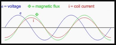
Remember the current in an inductor lags the voltage by 90 degrees and the magnetic flux level essentially follows the current flow. So you would need to switch off at the peak of the mains voltage
to ensure the flux was at a minimum in the core.You might like this, a 200va toroid. Just over 10 amps inrush current on the first cycle...
Transformer Inrush Current - Surprise! - YouTube
Attachments
I've searched through but may have missed it. Can you draw a schematic of exactly what you have done with your wiring setup and also a model number or datasheet for your transformers.
Also, (although it's hard to tell from the photos) your psu boards look like they're on very short standoffs. Nothings shorting to the chassis underneath them?
Also, (although it's hard to tell from the photos) your psu boards look like they're on very short standoffs. Nothings shorting to the chassis underneath them?
I need some help on my ACA build.
One channel is OK,
I'm running 330 mA for headphone. It sounds great, [better than my commercially bought HP-amp], great soundstage.
The other channel gives instability. That is, the output flutters. DC movement/operating point. There is hissing and many pops, not too much though, about 100 mV.
I have
I have placed a 50 uF cap across one of the gates. Then the other.
I resoldered all pins. I now use SAVEBIT; and when I made the circuit I used silversolder. I even have used a small box of solder gum.
Then - -
I split up the circuit in two halves, each having a load resistor: (bottom Q1 into R=56ohm, top Q2 into 33 ohm after the source resistors so the bias circuit is operating correctly.)
I ordered a ready build circuit board on the Bay, out of frustration.
Still I like to know what I do wrong.
Any suggestions? I have been at this for many hours already.
On my F5 I had similar issues on one channel; solved it by resoldering the long leads to my output FETS (Toshiba TO3 types).
One channel is OK,
I'm running 330 mA for headphone. It sounds great, [better than my commercially bought HP-amp], great soundstage.
The other channel gives instability. That is, the output flutters. DC movement/operating point. There is hissing and many pops, not too much though, about 100 mV.
I have
- replaced all active components by now (IRF830's, Q4 2SK170, Q3 BJT) and the capacitors (output, DC/bias)
- replaced the two source resistors.
- scraped off some isolation from the traces wires on the PCB and soldered that [Maybe there is a small discintinuity??].
- replaced the gate resistors (increasing them)
I have placed a 50 uF cap across one of the gates. Then the other.
I resoldered all pins. I now use SAVEBIT; and when I made the circuit I used silversolder. I even have used a small box of solder gum.
- After all this, the flutter remains.
Then - -
I split up the circuit in two halves, each having a load resistor: (bottom Q1 into R=56ohm, top Q2 into 33 ohm after the source resistors so the bias circuit is operating correctly.)
- this way the output is stable and good
- the DC operating points of the drain of Q1 on the load resistor and the source of Q2 respectively are as expected.
I ordered a ready build circuit board on the Bay, out of frustration.
Still I like to know what I do wrong.
Any suggestions? I have been at this for many hours already.
On my F5 I had similar issues on one channel; solved it by resoldering the long leads to my output FETS (Toshiba TO3 types).
How have you altered the ACA to get your 330ma bias?
Are you measuring this flutter after the output coupling cap? If yes then can you also see this flutter on the other side of the cap.
You could try removing the input coupling cap C3 and seeing if the output is steady.
Also measure the output from Q1 source to the audio output in case you have some wiring issue.
Is the preset OK?
I made the R1/R2 at just a single .68 ohm; and the R3/R4 at a single 2.2 ohm; with the 2K2 bias-divider it gives 330 mA at 20 Volt V+.
Without the 2k2 bias voltage devider it becomes 250 mA about.
The flutter is there on all sides of the input and output caps. But I kept the circuit closed, so I expected that.
As your tips:
I will look what happens if I take out the capacitor C3 - in effect it keeps the DC and keeps the input.
And yes, silent as anything; replaced the existing inputcap C3 with a 10uF MKT there to close the loop, and it remains good.
C3 was the only part I had left in place . . . it was a 1uF mylar. On my sims 1uF works OK with my load of 50 ohms Fostex headphone.
THANKS MOOLY
I still have some overshoot now - more than there was before - but I will place a small cap across the R12. [I don't have that overshoot on the other channel.]
I will put the original C2 1000uF/16V and the C1 470uF I have for output back. (lower numbers, higher impedance is OK)
The preset gives me 10,5 Volt on the drain of Q1 with 20,0 volt V+. I can get it a bit lower if needed.
[It could very well be I had the preset wrong, easy to do because of the DC feedback. ]
Next I'll test the MUSIC.
Without the 2k2 bias voltage devider it becomes 250 mA about.
The flutter is there on all sides of the input and output caps. But I kept the circuit closed, so I expected that.
As your tips:
I will look what happens if I take out the capacitor C3 - in effect it keeps the DC and keeps the input.
And yes, silent as anything; replaced the existing inputcap C3 with a 10uF MKT there to close the loop, and it remains good.
C3 was the only part I had left in place
. . . it was a 1uF mylar. On my sims 1uF works OK with my load of 50 ohms Fostex headphone.THANKS MOOLY
I still have some overshoot now - more than there was before - but I will place a small cap across the R12. [I don't have that overshoot on the other channel.]
I will put the original C2 1000uF/16V and the C1 470uF I have for output back. (lower numbers, higher impedance is OK)
The preset gives me 10,5 Volt on the drain of Q1 with 20,0 volt V+. I can get it a bit lower if needed.
[It could very well be I had the preset wrong, easy to do because of the DC feedback. ]
Next I'll test the MUSIC.
So it looks like the input cap was maybe a bit leaky. Excellent.
If you lower the value of the input cap then the output of the ACA before the speaker coupling cap will try and increase to maintain the level.
It does this because part of the feedback is taken after that cap. What this means is that the ACA may distort (clip) on low bass notes as it tries to maintain output.
Try it on your sim with a 1uF and look at the output before and after the speaker coupling cap
It simmed with a 4 dB peak at 1 Hz low frequencies, but in practice it was no problem. There is a sim rise at about 200 kHz but little.
Indeed, the level before the output cap can increase to clipping. That can destabilize the amplifier maybe, at least I saw that lowering input ould set it offf now with 10 uF on input; (in test I now have 220uF output) I will revert to 1.000 uF output.
With 1 uF input; 470 uF output I had a stable 7 Hz to 270KHz.
The overshoot I [now still] have is a puzzle.
Could it be gate resistor mismatch?
In sim, specifically the bottom one is very sensitive, Q1 gate = 100 ohms and Q2 gate = 220 gives a 3dB peak in the sim at 500 kHz. With 330/820 the bandwidth reduces to 300 kHz (I measured 270 kHz in the other channel).
albert
If you lower the output cap then depending on load impedance things can worse still
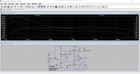
This is with 220uF output and 10uF input. The response is 'flat' at the speaker output with a gain of around 10db. All good... but is it...
To achieve that the output before the coupling cap rises massively (clipping!) as can be seen in the second trace.
Overshoot can caused by many things, even layout and grounding can play a part. Before chasing things around first make sure your scope (probe compensation) and input signal is good.
Attachments
Right - I guess the dual power supplies is what caught my eye.Any Bridged or Parallel ACA is dual mono...
At their most basic function, amps are modulated power supplies, so having a better power supply would seem to be a big improvement for this amp.
Mooly, you are quite right.
I reduced the input cap to 0.5uF in the sim and there is still a big overshoot on the lows with 470 uF, even on 50 ohms. So I simmed to 2200 uF output cap. Flat!

Output flat. Still there is a sort of bump. That is on the input summing node below 100Hz!

That bump also occurs in the stock version with 10 uF though below 10 Hz. .
I reduced the input cap to 0.5uF in the sim and there is still a big overshoot on the lows with 470 uF, even on 50 ohms. So I simmed to 2200 uF output cap. Flat!
By the way, .5uF/470uF sound great on the Fostex 50 ohm headphone, as long as there is no low freq component and you do not flip the on-off switch too quickly (I saw the scope trace jumping erratically after off/on cycle of 1 sec) .
Output flat. Still there is a sort of bump. That is on the input summing node below 100Hz!
That bump also occurs in the stock version with 10 uF though below 10 Hz. .
I’ve been experimenting with more and more switching PSU in these types of projects and with just a little post filtering I am finding them to be equal to, and in some ways superior to the big heavy linear supplies.
I have an NVVV switch mode supply on the ACA; it does need a good choke and filtering, there ís HF-residue. But almost gone with a 25 microHs/2200uF.
I asked them (the factory), if I could hang a 56.000 uF behind the supply (I have a box of those 8cm*16cm big cans) , 'sure they said'.
I plan to do that on the F6.
My F5 also has 4*those big cans but with a transformer. Well. Bigger is Better here too. .
I plan to do that on the F6.
My F5 also has 4*those big cans but with a transformer. Well. Bigger is Better here too. .
I’ve been experimenting with more and more switching PSU in these types of projects and with just a little post filtering I am finding them to be equal to, and in some ways superior to the big heavy linear supplies.
Slightly OT but have you got them working with F4 & F5 amplifiers? I much preferred wiring mains to an SMPS than making an entire circuit for 230v rectification. Too nervous 😬
It's not easy on a design like this to arrive at the most suitable cap values. You either go way over the top... or...
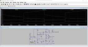
This is with a 35 ohm load and 0.5uF and 470u.. The input is a 1 volt peak square wave at 20 Hz (which shows this kind of thing well). The voltage across the load peaks at just over 4 volts and with obvious LF roll off, however the voltage in front of the cap is much larger in order to try and maintain the output.
This is with a 35 ohm load and 0.5uF and 470u.. The input is a 1 volt peak square wave at 20 Hz (which shows this kind of thing well). The voltage across the load peaks at just over 4 volts and with obvious LF roll off, however the voltage in front of the cap is much larger in order to try and maintain the output.
Attachments
Of course the ACA can run wil a wallwart supply (that is often a Meanwell one for instance, with a cord and plug).
I have choosen NVVV.
yes, 220V inside. But no 20-30Amp splurges and switching residues anymore twice every one of the 50/60 Hz, hard to get away. As we all know. Where we spend money on expensive rectifier boards, post filtering, lineair stages, shunts etc...
Just take time to create a good HF filter, here I used 25microH/220uF and .25ohm/3300uF - I could improve, leave that to my next build.
Caveat. The switching power - does have its own power line filtering caps (of course) and these are connected to the earth line. You have to have it earthed, otherwise inside the cabinet and having no outside connections (input cable) the chassis will have a slight stray power residue, say 80 volt to the touch. Not nice.
Even isolating the switching power case from the chassis (I put a piece of paper underneath) does not solve the problem.
When all is connected connected to input plugs that have an earth somewhere it is safe.
But otherwise, be prepared for a small jolt. It is not lethal.
I have had this n-times on transformer fed appliances too. Mostly with line input filters I used without having aan earthed socket.
Even isolating the switching power case from the chassis (I put a piece of paper underneath) does not solve the problem.
When all is connected connected to input plugs that have an earth somewhere it is safe.
But otherwise, be prepared for a small jolt.
It is not lethal. I have had this n-times on transformer fed appliances too. Mostly with line input filters I used without having aan earthed socket.
- Home
- Amplifiers
- Pass Labs
- Amp Camp Amp - ACA