I'm not able to parallel unless I change the internal wiring/or buy a 3 way switch and 1.8 it??
Look at post 5881
Fuxtor,
No need to change the switch or internal wiring to try it.
No need to change the switch or internal wiring to try it.
There have been a couple of pictorials posted before, this one is easiest to do and understand by Mutuano (Post #5881). It is all external and easily reversible too.
Link the two pins in the XLR socket with a suitable loop or wire as shown. That joins the left and right inputs together.
Link the two Black speaker connections with a wire. (The Red ones are already joined internally.)
If you have wired the rear switch from the build guide step 38, make sure it is Down as in the pictures.
That's it.
Spec is on the circuit diagram See enclosed.
I know nothing of the 'sequencer'. Is the output full all the time or can you turn it down? Ie have a volume or gain control? If in doubt, do not connect it. If you cannot 'turn it down' it will just clip very badly...
Just one more thing, if you are using the 24 volt smps (comes with the v1.6 and v1.8 kits) the 'bias' is set at 12 volts, not 10 volts.
More generally, you want to set the bias at about half the supply rail voltage (up to the 24v max). So pay careful attention to the input DC supply, and note that you can hook up a lower voltage supply but the bias will be off. I speak from experience with the early editions which is why I've "standardized" on 24V supplies for all my AmpAmps.
")
The question is HOW much are they differing? Are they biased to the same voltage with no inputs or outputs? I guess I am also assuming you used identical parts in both (including power supplies), but that is worth asking too.
I've now built 4 pairs of ACAs of different versions up to the latest since the 1.0 edition, and both channels each time run within 5C of each other (max). I was playing around with this about a month back when I fired every one up and measured the heat sink and MOSFET case temps after an hour, and later at full power. While there are differences between different versions of the ACA due to different current limiting resistors/biasing across the editions, within any one edition, both channels measured quite close after thermal stability was reached.
--Tom
I’m building up an aca using the diyadio parts kit and some funky heat sinks salvaged from vintage recording studio gear.
Because of the way the heatsinks are shaped, I’d like to mount the MOSFETs on them and then run wires to the circuit boards. The wires would be between 4.5 and 5.5 inches long. Is this likely to cause any problems? Are there any recommendations on wire gauge For these connections?
Because of the way the heatsinks are shaped, I’d like to mount the MOSFETs on them and then run wires to the circuit boards. The wires would be between 4.5 and 5.5 inches long. Is this likely to cause any problems? Are there any recommendations on wire gauge For these connections?
I would say it would probably be just fine. The wires to the drain and source should be fairly heavy gauge, lets say like 5 amp mains lead.
The wires to the gate can be much thinner. Be sure to mount the 100 ohm gate resistors right on the gate leg of the FET and not at the other end of the wire that goes to the PCB.
The wires to the gate can be much thinner. Be sure to mount the 100 ohm gate resistors right on the gate leg of the FET and not at the other end of the wire that goes to the PCB.
Sorry, I'm sure this has been addressed a few times but I'm looking for info about how to do a parallel mono config. I think I know how to do the hook up, but I'm not sure if I need to mod something internally? It's a v.1.6 , I never built the units but I am electronically capable...
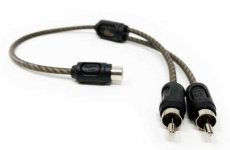
As well as the fily way shown earlier, one can just use 2 of these to split 2 channel feeds into 4.
dave
Attachments
I would say it would probably be just fine. The wires to the drain and source should be fairly heavy gauge, lets say like 5 amp mains lead.
The wires to the gate can be much thinner. Be sure to mount the 100 ohm gate resistors right on the gate leg of the FET and not at the other end of the wire that goes to the PCB.
Huh. Ok.... so you're saying bolt the MOSFET to the keratherm/heatsink, solder gate resistor to the gate leg and then the jumper wire from the resistor to the board?....
Speaker protection
Hi,
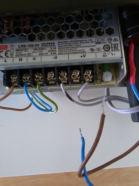
I'm a little concerned about the turn off thump as my 2 Pi speakers are quite sensitive. Page 192 mentions the addition of a 10000 if 25 v capacitor between the + and - leads from the power supply. From the photo below would just connecting the cap leads to the spare V+ and V- terminals be OK?
I would just like to double check.
Thanks,
Graham
Hi,
I'm a little concerned about the turn off thump as my 2 Pi speakers are quite sensitive. Page 192 mentions the addition of a 10000 if 25 v capacitor between the + and - leads from the power supply. From the photo below would just connecting the cap leads to the spare V+ and V- terminals be OK?
I would just like to double check.
Thanks,
Graham

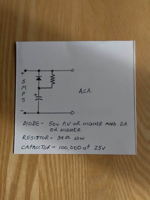
The first option would do very nicely, also acting as an additional filter above 150Hz.
Powerwise:
P = V x I = I x I x R = 1.4A x 1.4A x 0.1R = 0.196W (that's per channel, double for stereo)
so anything above 1W will do.
As a general rule (that I subscribe to) I would use a 2 - 5W ceramic resistor just so I can sleep sound at night.
Increasing R will work even better, but you have to observe the dissipation across the resistor.
And also remember you'll lose some voltage across that resistor and your output voltage will be slightly lower.
Attachments
- Home
- Amplifiers
- Pass Labs
- Amp Camp Amp - ACA