The PCB would be off-centered either 4cm to the front or 4cm to the rear, but yes, you can put them at least in two different positions in the UMS specification.
Rafa.
Edit: that is using the central PCB hole in the 6 -> 6 <- 6 scheme. If the rectangular holes are 8cm apart and 2cm off center (which they appear to be), then they might fit in the center of the UMS with two upper holes and the two MOSFETs, without lower support.
So there may yet be a third viable position, depending on the position of those 4 outer holes,which may yet fit also the 2cm pattern spacing.
Last edited:
Like Zer0p0intZer0, I'm confused about where to use the heavier gauge hookup wire (red and black in my supplied kit, although the pictures provided recently show blue and black heavy wires). I would think (and it LOOKS like) that the heavier gauge wire should be used for the power supply distribution and for the output to the speaker terminals. And it looks like the red, green, blue and white smaller gauge wires should be used for everything else. It would be good to know what the gauges are in case we have to go out and find more wire (or if we want to customize the colors we use for particular parts of the circuit).
Your assumptions are correct. The thicker 16AWG wires should be used for power (V+ and GND) and all speaker outputs.
The thinner wires are used for the LED’s, and input XLR/RCA wirings. 20AWG - 22 AWG should be sufficient.
If you do it right, you should have plenty of each gauge and color left over.
Best,
Anand.
it's a single R of approximately 23.5 ohms
0.235ohms
Thanks Anand. I had a look, I guess it's best into 8 ohms but will drive as low as 4 ohms?
Cheers,
Matt.
Others here have stated it’s fine to drive 4ohms loads. I did not have a good experience with my ACA balanced monoblock pair with Polk T15 or RT55 both being 8ohms (both sound ok with AB amps). Someone advised I try them with a pair of Martin Logan Motion 40. They’re more effficient and also 4ohms but the ACA has no problems driving them. The sound is great, through I have to drive my McIntosh preamp (output 2) pretty hard, 70% playing Yo-Yo Ma’s new album Six Evolutions. 70% would be ear damaging from my other amp and speakers on output 1. Heatsink hovers around 125F in a 76F room.
Hi Matt,
Thanks for the info on the hole spacing. Exactly what I needed - appreciated!
Cheers,
Bolke
No problem
")
Shorting the output should not cause any issue because there's C1 if the amplifier is "idling".
With full AC swing at its input and short at its output, the voltage drop across R1 and R2 (it's a single R of approximately 23.5 ohms) will increase the Q3 base voltage, make it conduct more and therefore reduce the voltage across C2 -> hence, the bias current would drop; and I expect it to drop below cut-off voltage if there's a "dead-short", so the Q2 MOSFETs will go into non-conducting state, and as the result, the Q1 current will disappear, making it incapable of amplifying any AC signal.
The same mechanism will "reduce" the power into 4 ohms speakers.
I'm politely asking the ACA Brain Trust (Mr Pass, Mighty ZM and other's who are the experts in this filed) to check what I wrote above... it might be wrong...
Thanks for the extra info, much appreciated.
Hi Brad,
We have your two emails / support tickets from 3 days ago, and today. They have already been discussed internally across all corners of the globe, with a slowdown caused by Hifi2000 tanning themselves on the beach right now recovering from shipping all those chassis. We should really tell people "we have received your email and your issue is being addressed" before we assign tickets rather than assigning a ticket, waiting for the answer / response to be formed, and then writing back. I'll ask our team to do that in the future, so you know "the wheels are in motion".
Expect to hear back from us within 24 hours.
I got my kit a little while ago, and still haven't warmed up the iron to dig in to the project. I didn't buy the chassis, because I'm going to mount the amps to a bulkhead in a sailboat I'm refitting. I found some big flat heatsinks I'm hoping will work; I guess I'll find out soon enough. If not, I'll find bigger ones.
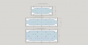
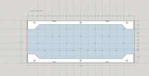
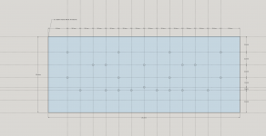
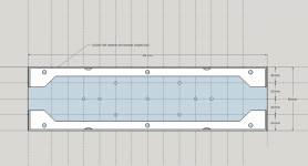
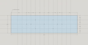
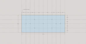
Yeah that would be because they aren't published anywhere yet. One foot in front of the other and all that.... Here's the 2Ux200, 2Ux300, and proposed 3U Franken-UMS. All this can be considered "unofficial", but as time allows, it should all become "official".
Attachments
-
 2U and 3U Montage with Brackets (X6).png59.3 KB · Views: 435
 -
 3Ux300 - With Brackets.png50 KB · Views: 107
 -
 3Ux300 - Line Diagram.png43.4 KB · Views: 106
 -
 2Ux300 - With Brackets.png32.4 KB · Views: 93
 -
 2Ux300 - Line Diagram.png44.9 KB · Views: 440
 -
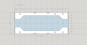 2Ux200 - With Brackets.png46.6 KB · Views: 439
 -
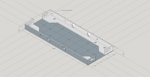 2Ux200 - With Brackets - ISO.png143.1 KB · Views: 440
 -
 2Ux200 - Line Diagram.png42 KB · Views: 437
Started the little ACA this morning and finished it this afternoon. It really is an easy build, many thanks to Nelson Pass and the team at DIYAudio for their hard work in designing and producing this little beauty. All biased up, listening tests next
Cheers,
Matt


Cheers,
Matt
Last edited:
The SMPS that comes with the ACA kit is outstanding: 23.98V at 0 amps in "idle", 23.96V at 4A constant current draw! That is a sag of only 2mV going from nothing to 4A. I "cooked" them for 10min - they hardly got warm... but kept the output voltage at 23.96V
My 6ohm/100W test resistor ( 2 X 12ohms / 50W resistors in parallel) got extremely hot!
They also have at the mains' side, a series fuse and a thermistor.
They are very well decoupled for a wide frequency range at the DC output side, so I expect a very low noise
Great quality. Kudos to Mr Pass for choosing them for ACA kits...
Almost forgot... both SMPS performed exactly the same down to a mV.
Last edited:
Yeah that would be because they aren't published anywhere yet. One foot in front of the other and all that.... Here's the 2Ux200, 2Ux300, and proposed 3U Franken-UMS. All this can be considered "unofficial", but as time allows, it should all become "official".
Nice work Jason.
Getting this sort of info out helps everyone (especially those going off script) plan accurately for their builds.
Much appreciated by me for one.
Hello, I built a pair of ACAs. They both bias fine and work fine. I am curious about one thing though. When I turn off one of the amps, the LEDs will immediately go dark. When I turn off the other amp, the LEDs will slowly fade to dark. I am wondering if this points to something I may have done incorrectly. I double checked all wiring and they are the same.
Thanks,
Alan
Thanks,
Alan
When I turn off the other amp, the LEDs will slowly fade to dark.
Alan
With around 1.45A of the constant current draw, the LED's should immediately go dark...
A voltage across C2 should be around 0.65V; bias current around 1.45A; i.e. voltage drop across R1 (or R2) should be 0.34V..... check the orientation of Q3.
You have a good working ACA, so -> compare...
Last edited:
No bias current? When idle for a while, do the heatsinks get as hot as the other one?When I turn off one of the amps, the LEDs will immediately go dark.
Yeah that would be because they aren't published anywhere yet. One foot in front of the other and all that.... Here's the 2Ux200, 2Ux300, and proposed 3U Franken-UMS. All this can be considered "unofficial", but as time allows, it should all become "official".
So nothing for the 3Ux400 (which I was planning to use for my M2X build) or is the 3U Franken_UMS just shifted down?
With around 1.45A of the constant current draw, the LED's should immediately go dark...
A voltage across C2 should be around 0.65V; bias current around 1.45A; i.e. voltage drop across R1 (or R2) should be 0.34V..... check the orientation of Q3.
You have a good working ACA, so -> compare...
No bias current? When idle for a while, do the heatsinks get as hot as the other one?
Actually, I rechecked this, and I guess it is a false alarm because both do the same thing. They immediately go about half dark, then fade out completely over the next 6 seconds. What I checked measures well, and both heat sinks on both amps are at about the same temperature by touch when idling for a while.
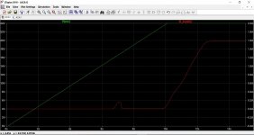
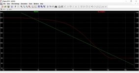
In simulation the current drawn by the amp decreases sharply below a certain supply voltage, actually down to single milliamp numbers, and so that would explain the LED behaviour.
This shows supply voltage vs current at power on and at power off. Current value is on the right hand side.
This shows supply voltage vs current at power on and at power off. Current value is on the right hand side.
Attachments
- Home
- Amplifiers
- Pass Labs
- Amp Camp Amp - ACA