While waiting on the ACA parts, I decided to model the AMP in LTSpice (I'm sure I'm not the first one to do it, but I wanted to try out the software and get more familiar with the AMP design, so I thought it was a nice idea).
And... I decided to model the Speaker as a fixed resistor (which I know it isn't, obviously, just for theoretical purposes), and decided to put a nice 8 Ohm speaker, my own 3.8 Ohm minimum Speakers (Totem Rainmakers), and a very demanding 2 Ohm speakers.
Here are the graphs on a 440Hz sine wave.
The 8 Ohm speaker shows the amp at a nice and symmetrical +-3V over the 1V input signal. Nice and clean (the FFT also show the nice 2nd harmonic predominance! Really neat!).

The (my) 3.8 Ohm speaker shows a more pronounced asymmetry on the + vs the - output signal, now only achieving +1.8V vs the -2.8V. Also, the amplitude of the amplificated signal starts to decrease over time.

The theoretical 2 Ohm speaker shows this behavior to greater extents.

Obviously this is all theoretical, but that certainly does not bode well for my speakers. Nothing we didn't already knew, but a nice confirmation at any rate") .
.
Hope someone else finds this interesting, if not, just ignore my post.
Best regards,
Rafa.
Edit: Maybe I need to let the simulation run for some seconds so the capacitors get a chance to charge? Would the software take that into account?
Edit 2: The 2Ohm run after 60 seconds is now more stable, but shows some clipping on the positive crests and the same asymmetry as before:

And... I decided to model the Speaker as a fixed resistor (which I know it isn't, obviously, just for theoretical purposes), and decided to put a nice 8 Ohm speaker, my own 3.8 Ohm minimum Speakers (Totem Rainmakers), and a very demanding 2 Ohm speakers.
Here are the graphs on a 440Hz sine wave.
The 8 Ohm speaker shows the amp at a nice and symmetrical +-3V over the 1V input signal. Nice and clean (the FFT also show the nice 2nd harmonic predominance! Really neat!).
The (my) 3.8 Ohm speaker shows a more pronounced asymmetry on the + vs the - output signal, now only achieving +1.8V vs the -2.8V. Also, the amplitude of the amplificated signal starts to decrease over time.
The theoretical 2 Ohm speaker shows this behavior to greater extents.
Obviously this is all theoretical, but that certainly does not bode well for my speakers. Nothing we didn't already knew, but a nice confirmation at any rate
.Hope someone else finds this interesting, if not, just ignore my post.
Best regards,
Rafa.
Edit: Maybe I need to let the simulation run for some seconds so the capacitors get a chance to charge? Would the software take that into account?
Edit 2: The 2Ohm run after 60 seconds is now more stable, but shows some clipping on the positive crests and the same asymmetry as before:
Last edited:

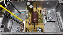
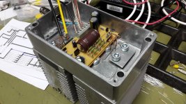
First channel running with 2SK369. Still only lukewarm after 20 minutes. Top of case from the mosfets is as cool as the heatsinks on the outside. The decade of 1W metal film resistors is actually hotter than the semiconductors.
Attachments
JáAny icelanders out there?
í 30 gráðu hita í Noregi."Yes, but in 30 degrees C in Norway."
Last edited by a moderator:
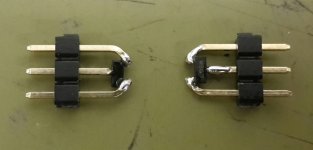
Did a quick test with three other JFETs. J112 with -3,8VGSoff, 8,5 gfs and >12mA IDSS is working fine, just like te SMD MMBF4393 with -2,2V, 8,5 gfs and >12mA. The fake J310 with -1,8V, 2,3 gfs and only 2mA IDSS didn't work.
I'll re-test the working ones with regard to THD performance, but that'll have to wait some days.
Here's a photo of how I prepared the SMDs for easy perfboard use.
I'll re-test the working ones with regard to THD performance, but that'll have to wait some days.
Here's a photo of how I prepared the SMDs for easy perfboard use.
Attachments
Power Supply for ACA v1.6
Hey guys!
Quick question. I found a Meanwell GS120A24-P1M power supply. It has the same exact specs as the GST120A24-P1M except for this:
The single-output green adapter is a Class I power unit which meets standards for Level VI energy efficiency. With efficiency up to 91% and the extremely low no-load power consumption of less than 0.15W, the GST120A device saves energy whether in operating mode or standby mode.
Does this matter in this application?
Thanks!
a picture worth a thousand words? Of course if you wanted to spend a bit of time with drill or skinny rat-tail file, you could get those Neutrik XLR jacks to align correctly
Wow. I never would have thought of that on my own...
In all seriousness though, the lesson illustrated by leaving those jacks as-is isn't to make it beautiful, it's to use what you have on hand, a laudable undertaking in DIY.
Also, when I get shipment of the actual XLR jacks that will be provided in the kit, I will use those to make the updated guide for the next ACA revision, and the updated photos will match the actual parts, and I won't have a couple of filed-out back panels to make the interior shots look bad.
The new power switch location and the new use of existing back panel switch will make enough changes to the guide that I'll need to re-shoot about 25-35% of the photos by my count...
Hey guys!
I found a Meanwell GS120A24-P1M power supply.
It's 24V 5A, and according to the datasheet has the proper plug.
The differences you are quoting are 100% sales and marketing technobabble.
Use it, it's perfect!!
It's 24V 5A, and according to the datasheet has the proper plug.
The differences you are quoting are 100% sales and marketing technobabble.
Use it, it's perfect!!
Sweet! Thank You 6L6. I notice you are down in Denver, I live in Windsor. Once I get the kit, can I contact you, if I have any questions?
Also, one of my best friends works for a very large electronics distributor and I can get these GS120A24-P1M power supplies for $35 shipped or (2) for $65. I don't mean to take any sales away from the DIY Store, but this saves everyone some money. Not sure how many I can get, but if interested email me at mraudioguru@gmail.com.
Thank you for sharing the photos, and I'm sure we would all like to see more!
You're welcome! I'll surely post some more pictures of the finished amps. Unfortunately I forgot to order some RCA connectors, so this won't happen tomorrow
Hi all. Hoping for some troubleshooting advice on my ACA. Boards are #1b, with both sitting in a single chassis with a torroidal power supply (and 8 x 22,000uf filter caps.)
After many lovely hours of trouble-free operation, I now have no output on the right side. There were no warning signs before it happened, either -- no pops, no distortion or degradation, no diminished volume. Moreover, nothing got disconnected or moved around. Just turned it on one day and had no right channel. So whatever happened happened during power up or power down, it would appear.
The right LED remains functional (and equally strong as on the left,) and a visual inspection of the guts doesn't show anything burned, as far as I can tell.
An excessive number of photos are at this link, would be glad for other eyes: Shared album - Ellery Gould - Google Photos
Any suggestions on where to start, and what a likely culprit might be?
Two important notes: First, I didn't build this. Got it in a trade a couple years ago, so I don't know if there were departures from the standard build, other than the power supply.
Second thing to mention is that I'm pretty much a newbie on this stuff. I put together a Bottlehead Crack several years back and I know my way around a soldering iron a bit from years of tinkering with guitar electronics, but that's the extent of it. In other words, no instruction or advice can be too pedantic and I welcome all of it.
Thanks!
P.S. I missed the store buy TWICE for the new kits ... but I'm hoping this repair project gets me primed and ready for a new build from scratch soon!
Where to start? That's easy. You have one working and one non working channel. Start by measuring voltages. Take schematics, and draw voltages in each spot you can reach and measure. Write in blue for working chanel, write in red ink for not working.
Some cleaver people here will tell you right away what is going on.
Good luck.
Some cleaver people here will tell you right away what is going on.
Good luck.
A guess: sounds like the V+ lead has enough of a connection to light the LED: but not able to sink the current to run the amp. That can start back at the connector or be at the solder joint at the circuit board. (Or both).
Another thing I see is it looks like poor solder joints all the way through. The blue resistors, for example don't look like they have much on the visible traces.
hope that helps!
Another thing I see is it looks like poor solder joints all the way through. The blue resistors, for example don't look like they have much on the visible traces.
hope that helps!
Hi all. Hoping for some troubleshooting advice on my ACA. Boards are #1b, with both sitting in a single chassis with a torroidal power supply (and 8 x 22,000uf filter caps.)
After many lovely hours of trouble-free operation, I now have no output on the right side. There were no warning signs before it happened, either -- no pops, no distortion or degradation, no diminished volume. Moreover, nothing got disconnected or moved around. Just turned it on one day and had no right channel. So whatever happened happened during power up or power down, it would appear.
The right LED remains functional (and equally strong as on the left,) and a visual inspection of the guts doesn't show anything burned, as far as I can tell.
An excessive number of photos are at this link, would be glad for other eyes: Shared album - Ellery Gould - Google Photos
Any suggestions on where to start, and what a likely culprit might be?
Two important notes: First, I didn't build this. Got it in a trade a couple years ago, so I don't know if there were departures from the standard build, other than the power supply.
Second thing to mention is that I'm pretty much a newbie on this stuff. I put together a Bottlehead Crack several years back and I know my way around a soldering iron a bit from years of tinkering with guitar electronics, but that's the extent of it. In other words, no instruction or advice can be too pedantic and I welcome all of it.
Thanks!
P.S. I missed the store buy TWICE for the new kits ... but I'm hoping this repair project gets me primed and ready for a new build from scratch soon!
Mraudioguru - Yes, absolutely! Heck, come down and you can test them with my rig.
Thank you sir! I might just take you up on that. Would love to meet you.
- Home
- Amplifiers
- Pass Labs
- Amp Camp Amp - ACA