If you have actually achieved 90dB open-loop gain all the way up to 10khz using one stage less than most people, then they are probably going to be angry, particularly the jealous ones.
OLG 90 db at 10 kHz? Impossible! really about 60-70 db, maybe.
More comments after giving a quick read to the other thread:
If you have actually achieved 90dB open-loop gain all the way up to 10khz using one stage less than most people, then they are probably going to be angry, particularly the jealous ones. I like that kind of technical challenges.
OLG at 2MHz≥70dB!
OLG at 2MHz≥70dB!
And your measurements at 100kHz/cca100W/4R ...
http://www.federmann.cz/images/stories/Nf/HQQF/504/100kHz_3.jpg
Sorry to interrupt you, but if I am not mistaking, Mr. Lin was first ")
Lin, H.C, Quasi Complementary transistor amplifier, Electronics, Sept 1956.
I ask all of you excuse me first of all... I am not going to teach anybody...
the only goal, I am trying to remind some facts
so all these amplifiers consist of three parts:
1. differential pair
2. current amplifier
3. power transistor indeed
thats all... plenty of variations but the same idea
another thing I'd like to clear for myself: total gate charge for IRFP9240 is equal to 44 nC. so if we calculate avarage gate current (of course I meen half period) at frequency of 20 kHz, we get I=Q*(2f), were Q is charge, f - frequency. it is not strict equation, only for geting order of the value))
so I = 2E-3 A. Am I wrong? seems no... so for 10 transistors we get current about 20 mA, mayby a little bit more...
nevertheless, I've seen for many times advises to use drivers with capability up to 1A or even more... what for? to eliminate the "error" between input and output? I meen to eliminate the difference between actual and expected output signal...
Lin, H.C, Quasi Complementary transistor amplifier, Electronics, Sept 1956.
I ask all of you excuse me first of all... I am not going to teach anybody...
the only goal, I am trying to remind some facts
so all these amplifiers consist of three parts:
1. differential pair
2. current amplifier
3. power transistor indeed
thats all... plenty of variations but the same idea
another thing I'd like to clear for myself: total gate charge for IRFP9240 is equal to 44 nC. so if we calculate avarage gate current (of course I meen half period) at frequency of 20 kHz, we get I=Q*(2f), were Q is charge, f - frequency. it is not strict equation, only for geting order of the value
)) so I = 2E-3 A. Am I wrong? seems no... so for 10 transistors we get current about 20 mA, mayby a little bit more...
nevertheless, I've seen for many times advises to use drivers with capability up to 1A or even more... what for? to eliminate the "error" between input and output? I meen to eliminate the difference between actual and expected output signal...
an amp that is flat to 20kHz probably has a low pass filter at it's input of ~100kHz to 300kHz.
If a transient comes along (interference or otherwise) the amp will try to pass that fast change through to the output.
If it rises at ten times faster than a full voltage 20kHz sinewave signal then it will charge the output transistor loading using ten times as much current.
Your 20 to 30mA becomes 200 to 300mA. Now apply a bit of temperature and voltage de-rating to your drivers and you'll discover that a 300mA driver cannot reliably supply fast transients to the output devices.
OLG at 2MHz≥70dB!
That would amount to a 6GHZ gain/bandwith product at 2mhz frequency...
Such a topology , moreover as simple as your implementation
can in no way achieve such numbers.
Please, stop misleading the general public with such disney world
like stories...
an amp that is flat to 20kHz probably has a low pass filter at it's input of ~100kHz to 300kHz.
If a transient comes along (interference or otherwise) the amp will try to pass that fast change through to the output.
If it rises at ten times faster than a full voltage 20kHz sinewave signal then it will charge the output transistor loading using ten times as much current.
Your 20 to 30mA becomes 200 to 300mA. Now apply a bit of temperature and voltage de-rating to your drivers and you'll discover that a 300mA driver cannot reliably supply fast transients to the output devices.
AndrewT, thank you for explanation! of course you are quite right. sinwave signal and musical signal are vary different things. (I should be proud of myself now
) becouse of presence of high level harmonics...so, to amplify correctly sharp rises-on, bandpass should be really up to 100 kHz for example...
you know, one feeling is contineously present in mind... if it is so easy, why nobody can repeat such amplifier? why the net is plenty of 100-200 Watt AB-class amplifiers, and as I can realise nobody has got 1000 Watt made by himself? Are they useless? I doubt... The only amps of such kind I've ever heard about are industrial Crown's , Yamaha's etc.
I am sorry for my childhood histories, but 'dejavu' feelings comes anew... when I've built my first two transistors amp (two stages of CE ) I was so inspired, that I connected 3-d CE transistor)) (input and output resistance were so far from me at that time ))
now looking at this multiplication of output MOSFETs... too good to be true))
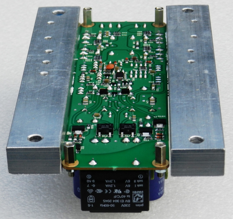
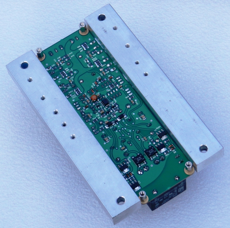
I'll post a picture of inner view Yamaha's amp, if you dont mind...
a piece of paper is cutted and attaced between aluminiums radiators. it is curved by manufacturer in the specific way. !!! they try to make cooling conditions more uniform for their transistors...
I am sorry, but like a complete DUMMY I surpose, that all such homebrew amp shoul work... But only for a short time)) or longer, but with the output power of 10-th part of its nominal.
Has anybody ask himself a question about STABILITY of output stages? Yes, I know that there are resistors in emmiter or source circuits, transistors are placed on thick aluminium radiator, mayby with forsed air circulation...
that is needed, but is that sufficient??? maybe not... those elements seems too slow, too inertial for possible quick distortions of current distributions between output transistors... or no???
he only thing I am completely sure - that big corporations they know something, that we don't! ;-)))
once more sorry... sincerely yourth DUMMY))
I am sorry for my childhood histories, but 'dejavu' feelings comes anew... when I've built my first two transistors amp (two stages of CE ) I was so inspired, that I connected 3-d CE transistor
)) (input and output resistance were so far from me at that time ))now looking at this multiplication of output MOSFETs... too good to be true
))I'll post a picture of inner view Yamaha's amp, if you dont mind...
a piece of paper is cutted and attaced between aluminiums radiators. it is curved by manufacturer in the specific way. !!! they try to make cooling conditions more uniform for their transistors...
I am sorry, but like a complete DUMMY I surpose, that all such homebrew amp shoul work... But only for a short time
)) or longer, but with the output power of 10-th part of its nominal. Has anybody ask himself a question about STABILITY of output stages? Yes, I know that there are resistors in emmiter or source circuits, transistors are placed on thick aluminium radiator, mayby with forsed air circulation...
that is needed, but is that sufficient??? maybe not... those elements seems too slow, too inertial for possible quick distortions of current distributions between output transistors... or no???
he only thing I am completely sure - that big corporations
they know something, that we don't! ;-)))once more sorry... sincerely yourth DUMMY
))another thing I'd like to clear for myself: total gate charge for IRFP9240 is equal to 44 nC. so if we calculate avarage gate current (of course I meen half period) at frequency of 20 kHz, we get I=Q*(2f), were Q is charge, f - frequency. it is not strict equation, only for geting order of the value
so I = 2E-3 A. Am I wrong? seems no... so for 10 transistors we get current about 20 mA, mayby a little bit more...
nevertheless, I've seen for many times advises to use drivers with capability up to 1A or even more... what for? to eliminate the "error" between input and output? I meen to eliminate the difference between actual and expected output signal...
You are mistaken.
Currents at 100kHz and Upp = 160V
An externally hosted image should be here but it was not working when we last tested it.
That would amount to a 6GHZ gain/bandwith product at 2mhz frequency...
Such a topology , moreover as simple as your implementation
can in no way achieve such numbers.
Please, stop misleading the general public with such disney world
like stories...
Sorry, only 70 dB at 200kHz.
An externally hosted image should be here but it was not working when we last tested it.

- Status
- This old topic is closed. If you want to reopen this topic, contact a moderator using the "Report Post" button.
- Home
- Amplifiers
- Solid State
- amp 1000W/2000W, IRFP240/9240